
![]()
![]()
![]()


To measure the current of the motor under testing, it is detected from the voltage at both ends of a 0.1 shunt resistor as shown in the figure 1.
Since the voltage supplied to the motor under testing is reduced by the shunt resistance, a SENSING terminal is provided to compensate for it, and the relay is switched. This relay is turned ON with the MOTOR ON operation, but it will be released for a very short time.
Depending on the DC power supply, the open state of this SENSING terminal generates a spark-like high voltage as shown in figure 2, and alarm protection is operated.
<Countermeasure>
Insert the bold solid line Rx2, C1 and C2 in the figure 1 to make sure the initial voltage is applied to the SENSING terminal even if it is in open state. The following value is reference value. In fact, please select the one whose spark in figure 2 falls within the voltage which does not adversely affect the motor to be tested. Attach the condenser by paying attention to its polarity. Please confirm to the DC power supply manufacture.
R: 100 Ω
C1: 1000 µF/ Please use the resistance voltage against to the maximum voltage of the DC power source for the motor. (50 V to 100 V)
C2: 0.1 µF Ceramic condenser/ Add this when the spike type spark in C1 cannot be cut off.
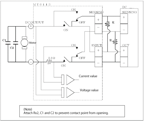
<Figure 1>
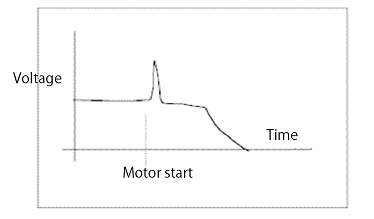
<Figure 2>
Revised:2017/05/31
