
![]()
![]()
![]()


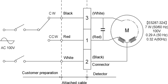
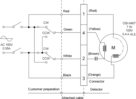
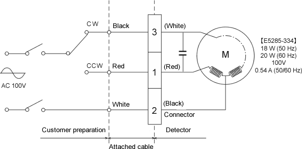
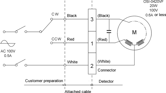
The following figures are the wiring method when the CW/CCW switching of the SS series torque detector attached motor is modified to external switching. The power connector is changed from 2-pin to 4-pin. 5 m cable is attached (one side: RM15QPS-4SA – one side: open)
1.External control to switch the motor rotation direction of the SS-002 to SS-200, SS-2050 to SS-2200
The detector which has OM sticker on the top surface
| Pin No. | 1 | 2 | 3 | 4 |
|---|---|---|---|---|
| Detector | Red | Black | White | Open |
| Cable | Red | White | Black | Green |
The detector which has no OM sticker on the top surface
| Pin No. | 1 | 2 | 3 | 4 |
|---|---|---|---|---|
| Detector | Red | Brown | Orange | Yellow |
| Cable | Red | White | Black | Green |
2.External switching SS-500 to SS-202
The detector which has OM sticker on the top surface
| Pin No. | 1 | 2 | 3 | 4 |
|---|---|---|---|---|
| Detector | Red | Black | White | Open |
| Cable | Red | White | Black | Green |
The detector which has no OM sticker on the top surface
| Pin No. | 1 | 2 | 3 | 4 |
|---|---|---|---|---|
| Detector | Red | White | Black | Open |
| Cable | Red | White | Black | Green |
Caution
1. Please use approx. 3A of the contact capacity of the relay.Revised:2008/06/23
