
![]()
![]()
![]()


The following figures are the wiring method when the CW/CCW switching of the MD series torque detector attached motor is modified to external switching. The power connector is changed from 2-pin to 4-pin. 5 m cable is attached (one side: RM15QPS-4SA – one side: open)
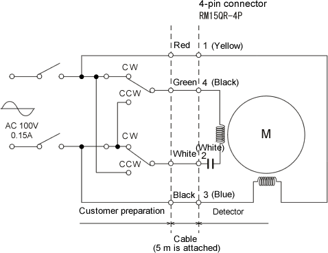
| Pin No. | 1 | 2 | 3 | 4 |
|---|---|---|---|---|
| Detector | Yellow | White | Blue | Black |
| Cable | Red | White | Black | Green |
Caution
1. Please use approx. 3A of the contact capacity of the relay.
2. CW and CCW directions which mentioned in above is the shaft rotation direction which is viewed from the drive side of the detector. The rotation direction of the detector and attached motor are necessary to be rotated in reverse direction.
Revised:2008/06/23
