
![]()
![]()
![]()


(1)Power supply
<1> AC adaptor connection
Remove the cover cap of the plug for the AC adaptor (accessory) from the round connector hole and insert to the linear gauge. The AC adaptor operates on AC 100 V. When the AC adaptor is not being used, always be sure to replace the cover cap to prevent from dust entering the gauge.
<2> Use of the battery power
In order to recharge the battery, connect the AC adaptor and turn the power switch off. The battery will be fully charged in 16 hours. Avoid charging for more than 16 hours. (Use the AC adaptor for long hours with caution.)
Remove the AC adaptor and switch the power on. When fully charged, the battery will support continuous operation for 8 hours. When it is not being used, switch the power off.
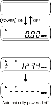
When the voltage of the rechargeable battery falls below a reference level, "B" mark appears in the LCD display.
When "B" mark appears, the battery should be recharged with connecting to the AC adaptor.
<3> AC adaptor operation
Connect the AC adapter and use the instrument with the power switch on. During this time, it is continued to be charged, so that it will not power off even if the power supply from the AC adaptor is cut off. Use the power switch to turn it off. Don’t use for a long hours with the connection of the AC adaptor.
<4> When 0.00 mm (zero) doesn’t appear, even though the power is on (display nothing)
The display may show nothing (0.00 mm doesn’t appear), even though the power is on when you use the instrument for the first time or you have not been used the instrument for several months. It is because the battery is electrically discharged so please recharge the battery.
<5> Zero reset operation
When the power is switched on or the reset switch is pressed for briefly and released at a short time, the display shows zero. The spindle position at the time is zero point.
<6> Count direction selection
The measurement value is incremented or decremented depending on the direction of the spindle movement. The direction can be selected by the ▲ or ▼ mark in the display. The direction is changeable with the direction switch "+/-".
▲ : Increment counting (+ direction) when the
spindle is pushed in.
▼ : Decrement counting (- direction) when the spindle is pushed
in.
Caution:
When the direction is changed during the measurement by pressing the
direction switch, the sign of the displayed value is changed at the
same time. Select the proper direction before starting the
measurement.
<7> MAX/MIN measurement mode
<8> Spindle movement
<9> Printer connection
It is possible to connect the output connector and the optional printer. When you switch on the print switch of the printer, you can print out the displayed value.
Revised:2001.01.12
