![]()
![]()
![]()
Digital Gauge FAQ


The DG-4320/4340 Digital Gauge Counter can be used for the dimension measurement combined with the GS series Gauge Sensor. Also, it can be operated as the counter combined with the Rotary Encoder.
(1) Front panel
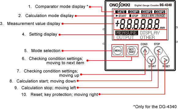
1. Comparator mode display (*Only for the DG-4340)
GATE: Displayed when the comparator functions have been stopped by external input.
COMP1/COMP2/COMP3: Displayed when comparator 1, 2 or 3 output is ON.
2. Calculation mode display
START: Displayed when the MAX, MIN or RANGE calculation has started.
MAX/MIN/RANGE: Display the calculation mode (MAX/MIN/RANGE).
3. Measurement value display
Display each data of the instantaneous values, MAX, MIN or RANGE calculated values.
4. Setting display
Display each data when setting or checking the parameter values.
5. Mode selection
Used to select the measurement mode or setting mode.
6. Checking condition settings and moving to next item
Used to check the setting conditions or to move to the next item of the setting condition.
7. Checking condition settings and moving up
COND: Used to check the condition settings.
∧: Moves up the cursor to set condition.
8. Calculation start and moving down
START: Used to start the MAX, MIN or RANGE calculation. (Past data is erased automatically.)
∨ : Moves down the cursor to set conditions.
9. Calculation stop and moving down
STOP: Used to stop calculation
< : Moves left the cursor to set conditions.
10. Reset/ key protection/ moving right
RESET: Used to reset instantaneous values and each calculated value. Values are not reset when calculation has started. You must stop calculation first to reset values. Pressing and holding this key for at least 2 seconds to turns on key protection. When key protection is set, the message "KEY PROTECT" appears when any key is pressed. To release key protection, press and hold this key again for at least 2 seconds.
> : Moves right the cursor to set conditions.
(2) Rear panel
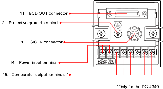
11. BCD OUT connector
The connector for BCD output, control output or external command signal input.
12. Protective ground terminal
Always ground the device to prevent electric shocks and eliminate noise.
13. SIG IN connector
Inputs signals from the gauge sensor or rotary encoder.
14. Power input terminal
Input the 100 V to 240 V AC (50/60 Hz) power supply.
15. Comparator 1/2/3 output terminals (*only for the DG-4340)
When each comparator is ON, each signal is output from one make contact.
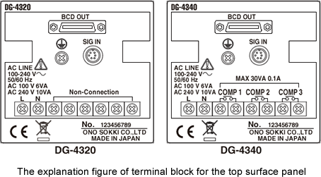
(3) A sticker on the top surface of the device
Revised:2000/12/08