
![]()
![]()
![]()


Set the upper limit and lower limit to the UPPER digital switch and LOWER digital switch of the front panel which become criteria of the pass-fail decision.
Pass-fail decision is as follows.
| Decision criteria | Decision | Display and output of decision result |
|---|---|---|
| LOWER set value ≥Display value | LOWER |
|
| LOWER set value < Display value < UPPER set value | OK |
|
| UPPER set value ≤Display value | UPPER |
|
Consider which is the counting, positive (+) or negative (-) when the gauge sensor spindle is pushed in, where is the decimal point display position and where is the zero set point before you set the upper and lower values.
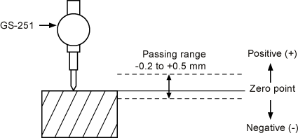
(Setting example 1) Range from -0.2 to +0.5 mm is determined as OK.
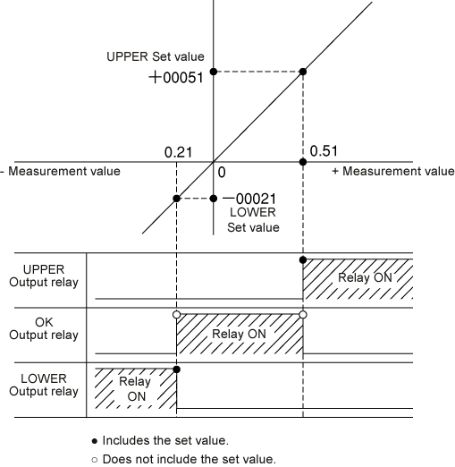
The resolution of the GS-251 and GS-1513A is 10µm. -0.20 is displayed when the measurement value is the lower limit -0.2 mm of the passing range. 0.50 is displayed when the measurement value is the upper limit +0.5 mm of the passing range. The value determined as OK does not include the set values specified by the LOWER and UPPER switches. Therefore, when -00021 is set by the LOWER switch and +00051 is set by the UPPER switch, a value in the range of -0.2 to 0.5 mm is determined as OK.
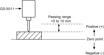
(Setting example 1) Range from +5 to +10 mm is determined as OK.
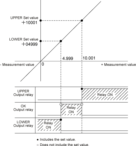
The resolution of the GS-5011 and GS-1630A is 1 µm. 5.000 is displayed when the measurement value is the lower limit +5 mm of the passing range. 10.000 is displayed when the measurement value is the upper limit +10 mm of the passing range. The value determined as OK does not include the set values specified by the LOWER and UPPER switches. Therefore, when +04999 is set by the LOWER switch and +10001 is set by the UPPER switch, a value in the range of +5 to +10 mm is determined as OK.
Revised:2000/12/08
