
![]()
![]()
![]()


This is an explanation of the timing chart of the signals which are inputted from the terminal block.
It is possible to input from the non voltage relay contact and open collector signal. We recommend you to input not from the BCD connector but from the terminal block in the connection with PLC (Programmable Logic Controller).
Although the signal response time from the BCD connector is faster than from the terminal block, please pay attention to the noise. For farther information, please refer to the instruction manual.
The example of the terminal block output circuit and PLC (Programmable Logic Controller) connection
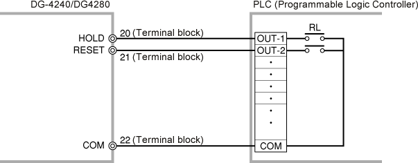
HOLD, RESET, GATE input circuit of the terminal block
1. HOLD input, BUSY input, Print command output timing chart
When you take the data into the PLC (Programmable Logic Controller), please make the BCD signal in a stable condition by processing the hold signal. Without processing the hold, the data cannot be read properly when you try to take the data in the timing of the BCD data changed.
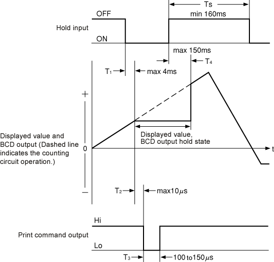
| T1 | Time from hold signal input to hold the displayed value and BCD output is maximum 4 ms. |
|---|---|
| T2 | Time from the holding of the displayed value and the BCD output to print command signal output is maximum 10 µs. |
| T3 | Print command signal pulse width; 100 to 150 µs. |
| T4 | Time from the release of the hold signal to the release of the hold state; maximum 150 ms. |
| T5 | Time from the release of the hold signal to the input of the signal again; minimum 160 ms. If the hold signal is input at shorter intervals than 160 ms, the print command signal may not be output. |
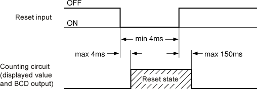
2. Reset signal timing chart
The reset input signal must have a pulse width of 4 ms or more. It takes up to 4 ms from signal reset input to reset state. It takes up to 150 ms from the release of the signal reset to the release of the signal reset.
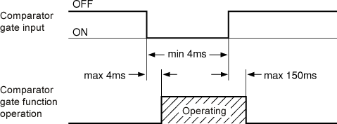
3. Comparator gate input signal timing chart
This is used when forcibly turned the pass-fail decision output off. The comparator gate signal must have a pulse width of 4 ms or more. It takes up to 4 ms from comparator gate signal input to its operation start. It takes up to 150 ms from the release of the signal reset to its operation stop.
Revised:2000/12/08
