
![]()
![]()
![]()


The BCD OUT circuit configuration for the DG-4240 and DG-4280 are the same.
The following shows you the recommended interface for the external device connection like PLC (Programmable Logic Controller) with the BCD OUT. For the BCD connector pin number, please refer to the "The explanation of the BCD OUT connector signal of the DG-4240 Digital Gauge Counter" and "The explanation of the BCD OUT connector signal of the DG-4280 Digital Gauge Counter.".
Recommended interface
1. BCD output, polarity output, decimal output, error output and print command output
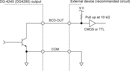
| Output type | Open collector output |
|---|---|
| Output IC | 74LS07 |
| Voltage resistance | Maximum 30 V For reliability improvement, it is recommended to use in the power system of 24 V or less. |
| Maximum synch current | Maximum 32 mA |
| Residual voltage | Maximum 0.5 V |
2. HOLD input, RESET input and BUSY input
Recommended circuits are as follows for the interface.
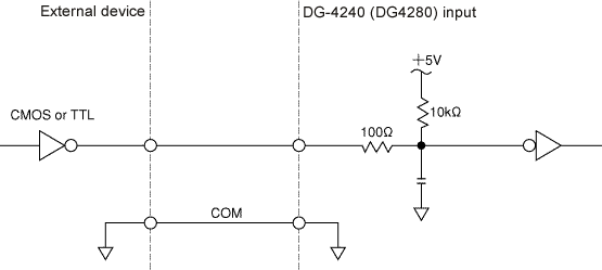
Low level input voltage |
0 to 1.4 V |
|---|---|
High level input voltage |
3 to 5.25 V |
Input impedance |
1 kΩ or more |
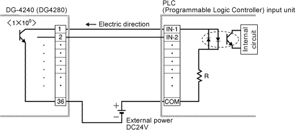
Connection with the PLC (Programmable Logic Controller)
1. BCD OUT
The BCD OUT signal is open collector output, so please connect to the input unit for the open collector input of the PLC (Programmable Logic Controller) side. (Voltage is between DC 12 V to 24 V.) Therefore, please be careful that if you connect the polarity of the external power reversely, the BCD output circuit will be broken.
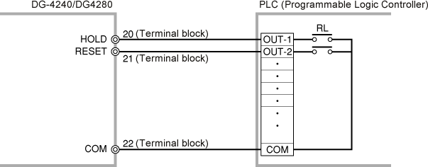
2. HOLD input, RESET input signal
The BCD input connector is for voltage signal input, so we recommend you to connect the PLC (Programmable Logic Controller) to the voltage output unit (TTL). When operating with the open collector or the relay contact point, error might occur from the noise depending on the environment of a working site. Recommend you to use the terminal block input when inputting at the contact point.
Revised:2000/12/08
