
![]()
![]()
![]()


This is an explanation of the signal connection of the rear panel.
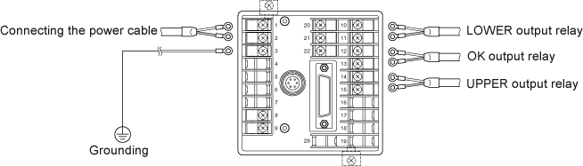
1.Connecting the cable
The M3.5 screws are used for the terminal block. Recommend to use the round shaped press-fit terminal available for the M3.5 screw to connect to the terminal block.
2. Grounding
Be sure to ground at the ground terminal (No. 3) for the safety and noise elimination. Ground at a single point with the ground terminal and do not implement crossover wiring.
| Grounding type | : Third class grounding or more (100 Ω or less) |
| Grounding line | : Soft copper wire of 2 mm2 or more (AWG 14) |
| Grounding extension | : Maximum 20 m |
3. Connecting the relay output
When inductive load is connected to the Relay output (No. 10 to 15) on the rear panel, the protection circuit can be used to reduce the back electromotive force and prevent damage to the relay contact.
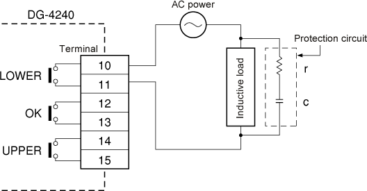
Selection guideline for c and r are as follows;
c: 0.5 to 1 µF to contact current 1 A
r: 0.5 to 1 Ω to contact voltage 1 V
However, they do not always coincide due to the properties of load and the unequal relay characteristics. Check by experimentation after considering that the c takes charge of discharge suppression effects during contact opening and the r plays a role of current limiting during next power on. Select the c with the voltage resistance of 100 to 300 V. Use the AC capacitor (without polarity) for the AC circuit. When load is a relay or solenoid, a reset time is delayed.
4. Connecting external equipment
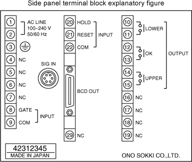
To input the PRESET GATE signal, HOLD signal and RESET signal from external equipment, connect the external equipment to the terminal block on the rear panel. For farther information, please refer to "The timing chart of the terminal block input signal of the DG-4240/4280 Digital Gauge Counter.".
5. Mounting the terminal block cover (option)
We are preparing the terminal block cover (DG-0420) as an option.
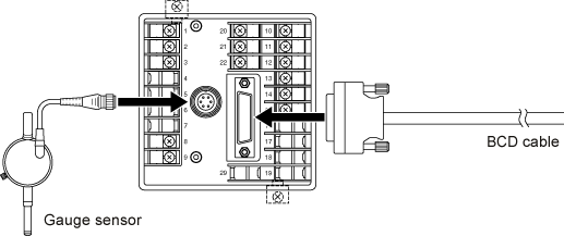
6. Connecting the GS senor and the BCD signal cable
Connect the gauge sensor signal cable and the BCD signal cable as following figure. We are preparing the AA8107 (3 m in length, one side open) as an option BCD connector signal cable.
Revised:2000/12/08
