
![]()
![]()
![]()


The DG-4120 Digital Gauge Counter can be used in combination with the gauge sensor to operate the measurement. All of the GS series latest and previous models can be conformed to the counter.
1. Front panel
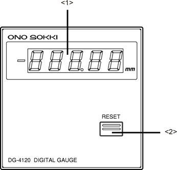
<1> Display
Display a measurement value using 5-digit numeric with the unit of mm. When a measurement value is negative, "-" is lit on the left side of the display. When measurement error occurs, the displayed value is flashed.(Please refer to the "Trouble shooting- Flashing of the display" page.)
<2> RESET switch
Resets the displayed value, BCD output data, error display and error output after pressing the switch.
1. Rear panel
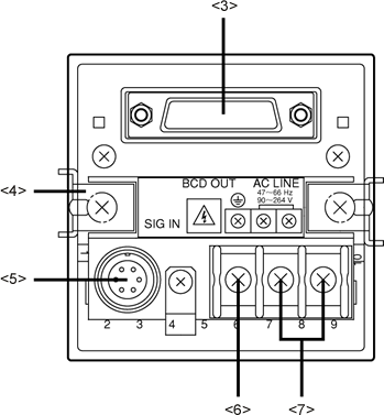
<3> BCD out connector
For further information, please refer to the "The explanation of the BCD OUT connector signal of the DG-4120 Digital Gauge Counter." page.
<4> Panel mounting fixture
Use this fixture to mount the DG-4120 to a panel.
<5> SIG IN connector
Connects the gauge sensor signal connector to this connector.
<6> Grounding terminal (Terminal screw)
This terminal must be grounded for safety in operation and noise elimination.
<7> Power supply terminals
Input the power supply voltage of AC 100 V to 240 V. The allowable range of the power supply voltage to be connected is 90 to 264 V AC.
Revised:2000/12/08
