![]()
![]()
![]()


This is an explanation of the recommended interface when connecting the external device and BCD out of the DG-4120 Digital Gauge Counter. The positive/negative logic selection is available.
1. When receiving by voltage
BCD output, polarity output, decimal point output and print commend output
Recommend circuit of the external device and the output specification of the DG-4120
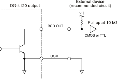
| Output type | Open collector output |
|---|---|
| Output IC | 74LS07 |
| Voltage resistance | Maximum 30 V For reliability improvement, it is recommended to use in the power system of 24 V or less. |
| Maximum synch current | Maximum 32 mA |
| Residual voltage | Maximum 0.5 V |
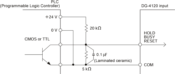
HOLD input, RESET input and BUSY input
Recommend circuit of the external device and the input specification of the DG-4120
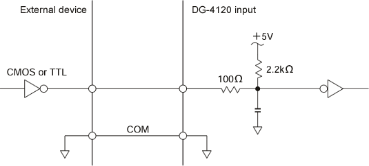
| Low level input voltage | 0 to 1.4 V |
|---|---|
| High level input voltage | 3 to 5.25 V |
| Input impedance | 1 kΩ or more |
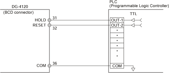
2. When connecting to the PLC (Programmable Logic Controller)
The BCD OUT signal is an open collector output, so please connect the input unit for the open collector signal (Voltage: DC 12 V to 24 V) to the PLC (Programmable Logic Controller) side. If the polarity of the external power is connected reversely, the BCD output circuit will be broken. Please be careful not to connect it reversely.
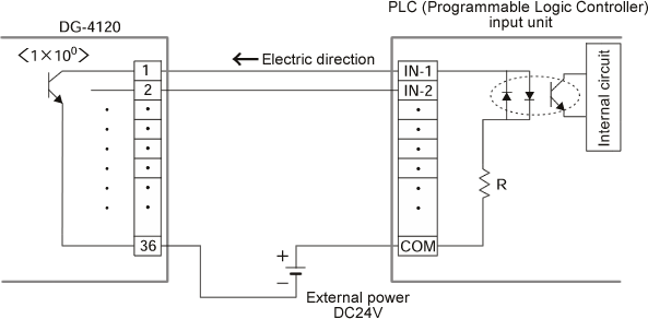
The DG-4120 input connector is for voltage signal input, so we recommend you to connect the PLC (Programmable Logic Controller) side to the voltage output unit (such as TTL). When operating with the open collector or the relay contact point, error might occur due to the noise depending on the working site environment. Please operate the suitable noise countermeasures. The following figure is an example of it.
Recommended voltage signal input
Example of noise countermeasure