![]()
![]()
![]()

How to display the sound data from the Sound Level Meter or Microphone as a sound pressure level by using the OS-2000 series basic (2)

From the 2.7 or later version of the OS-2000 series, the function that can calibrate the data file by using the calibration signal file recorded by the DR-7100 is added. The following is the sound data calibration method by using this function.
1. Import the calibration sound file and recorded data file to be calibrated into the OS-2000.
Please make sure to set the amplification degree of the recorder for calibration sound data and the recorder for recording data the same.
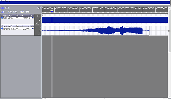
The upper figure shows the screen when the sound data recorded by the DR-7100 is imported to the OS-2000 series. The upper side is a data file of calibration sound (94 dB) and the lower side is a data file of engine intake noise. The unit is [V].
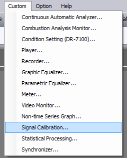
2. Start the calibration to the sound pressure by using the upper side calibration sound data file. Select the “Signal calibration” in the [Custom] of the OS-2000 tool bar. The signal calibration window is opened.
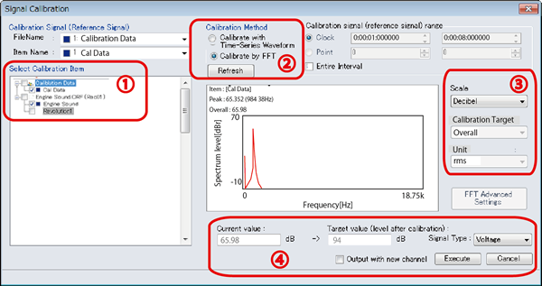
① Select the calibration sound recorded file as [Calibration Signal (Reference Signal)]. Then, select the data file to be calibrated from the [Select Calibration Item] and put a check mark on the box.
②Select [Calibrate by FFT] in the [Calibration Method]. [Entire Interval] is selected in the default setting in the [Calibration signal (reference signal) range. However, if it is selected as total length, it may too long or the signal is not stable at the start of measurement, select the range where the stable signal is outputted. (Please select between several seconds to 10 seconds.)
③Select [Scale] to [Decibel], [Calibration Target] to [Overall], and [Unit] to [rms].
④Select the [Target value (level after calibration)] to sound pressure level (94 dB in here) of the calibration sound, and click [Execute].
* If you want to write to a different channel without overwriting the data after calibration, put a checkmark in [Output with new channel].
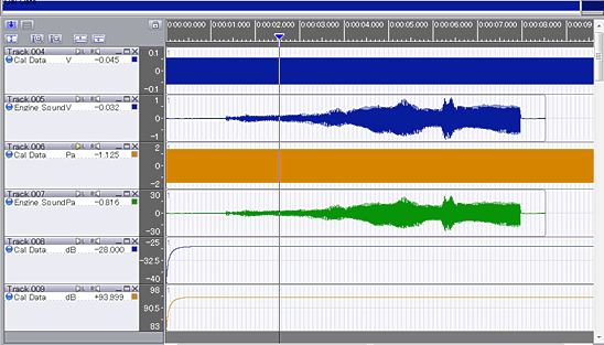
The file on the top is the original calibration sound data, and the third one is the calibration sound data after signal calibration. The second from the top is engine intake noise data, the forth from the top is data which performed signal calibration. The signal unit in the calibrated file is changed from [V] to [Pa]. The fifth from the top is the result of [Effective value calculation] of the calibration sound data on the top. The sixth from the top is the result of [Effective value calibration] of the calibration sound data after [signal calibration]. It becomes 93.999 dB from -28 dB.
Revised:2017/07/12