![]()
![]()
![]()


Adjust the offset volume to output the pulse signals of 1 P/R, 720 P/R or 360 P/R correctly. We recommend you to make adjustment while visually confirming the waveform by oscilloscope.
1. MONITOR output
|
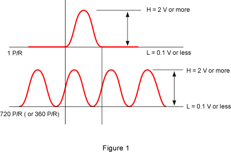
These are output connectors of the signal from the detector of CP-5100 and CP-5200. Check if the detector works normally or not by observing this waveform. Operational waveform of the CA-500A is shown in the Figure 1. Maximum voltage is ±15 V. It is depending on the fiber cable relay condition. When the amplitude is smaller than the figure 1, inspection for the detection side (CP series) is necessary.
|
2. Pulse output 1 P/R, 1/1 or 1/2 output connector
|
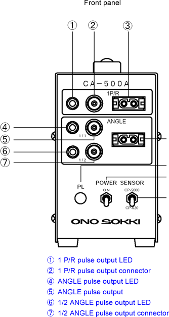
Output the 1 P/R signal from ②, and turn on (blinking) the LED ①. Output the ANGLE signal (for example 720 P/R) from ⑤, and turn on (blinking) the LED ④. The signal of ⑤ is made in half (for example 360 P/R) to output form ⑦ and the LED ⑥ is turned on (blinking). (When the signal frequency is fast, blinking of the LED looks like a lighting state.)
3. OFFSET adjustment
■1 P/R pulse output
|
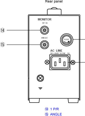
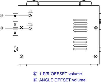
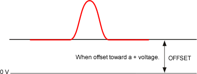
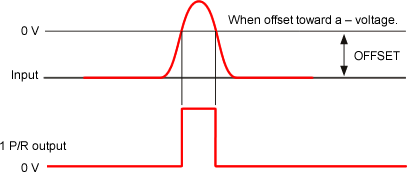
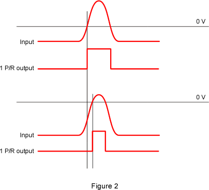
When the ⑫1P/R OFFSET volume is rotated, amount of DC signal is superposed to the input signal of 1 P/R as shown in the figure 2. The threshold value of pulse output is 0 V. The output timing of the pulse is as shown in the figure 2. Drive the engine for a suitable number of rotations. Fully turn the OFFSET volume to the clockwise direction (+ voltage of offset is applied) and slowly turn back to the counterclockwise direction to turn on the LED ①. When the volume is turned further more to the counterclockwise direction, LED is turned off. Adjust the volume at the position where the output waveform is stabilized.
|
|
|
■ANGLE pulse output
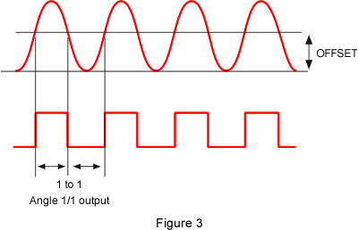
Operate the same adjustment method as 1 P/R by using ⑬ ANGLE OFFSET volume to stabilize the output pulse width as shown in figure 3. The LED ④ is turned on when output of 720 pulses is properly confirmed in one rotation. When you fully turn the OFFSET volume to clockwise direction, the offset of + voltage is applied.
|
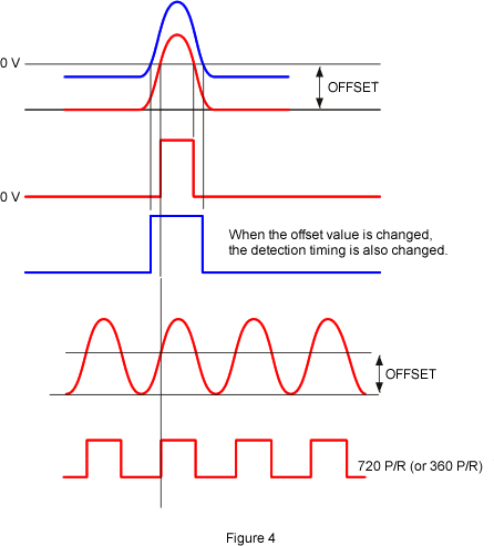
4. Timing of 1 P/R and ANGLE pulse output
The pulse width is changed depending on the adjustment state of OFFSET volume as described in 3. Check the output timing for each 1 P/R pulse and ANGLE pulse by monitoring them at the same time. Malfunction may occur when the rising (or falling) timing of 1 P/R pulse and ANGLE pulse are same due to the specification of the connecting device such as combustion analysis system. So please make minor adjustment of the 1 P/R OFFSET volume to shift the rising timing of them as shown in figure 4. This malfunction may also cause the disturbance of the blinking of the LED ④.
|
Revised:(2002/09/17)