![]()
![]()
![]()


To fix the LC-1100/SF-660B Spatial Filter Type Speed Detector by using the mounting fixture, please note followings;
1. Choose a safe position with a limited engine vibration at back and front or left and right side of the vehicle.
2. Change the fixing direction of the detector according to the fixing position.
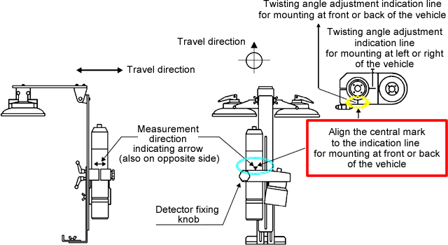
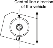
3. The detector can rotate freely by loosening the detector fixing knob in the holder part. So, make sure to align the measurement direction to the central line of the vehicle direction and fix.
1. Mounting at front or back of the vehicle
|
1. Firmly fix the mounting fixture plate orthogonal as much as possible to the central line of the vehicle.
2. Loose the detector fixing knob.
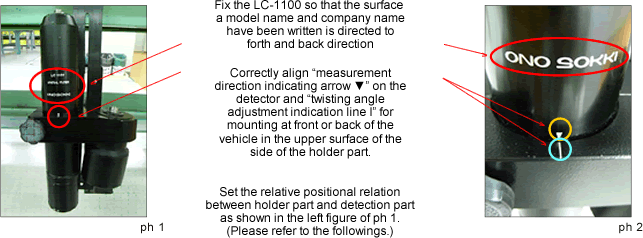
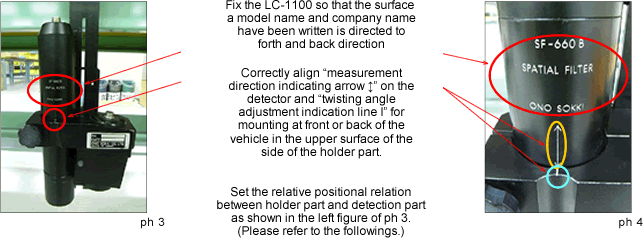
3. Realign the measurement direction indicating arrow ▼ in the detector surface to the twisting angle adjustment indication line when mounting at front or back of the vehicle in the holder part.
4. Firmly retighten the detector fixing knob before use.
Concrete example of mounting LC-1100 Spatial Filter Type Speed Detector
|
Concrete example when the use of the SF-660B Spatial Filter Type Speed Detector
|
2. Mounting at side (left and right) of the vehicle
|
1. Firmly fix the mounting fixture plate parallel as much as possible to the central line of the vehicle.
2. Loose the detector fixing knob.
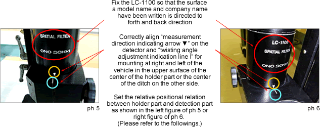
3. Realign the measurement direction indicating arrow ▼ in the detector surface to the twisting angle adjustment indication line when mounting at left or right of the vehicle in the holder part or the center of the groove in the opposite side.
4. Firmly retighten the detector fixing knob before use.
Concrete example when the use of the LC-1100 Spatial Filter Type Speed Detector
|
In the use of the SF-660B, adjust the fixing angle similar to the LC-1100 by using the measurement direction indicating arrow in the detector surface and the twisting angle adjustment indication line when mounting at left or right of the vehicle in the holder part or the center of the groove in the opposite side.
3. Special example when mounting at front or back of the vehicle
|
  |
<Caution>
Above method may cause a measurement error, so use it as an exceptional measure. Please realign the above arrow and line after the measurement.
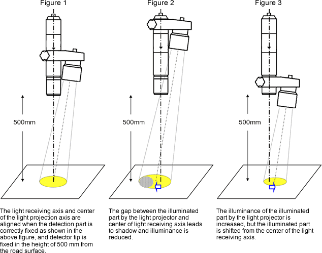
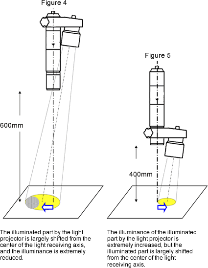
4. Relationship between the mounting position and illuminance of the LC-1100/SF-660B Spatial Filter Type Speed detector
When entire detector is spaced apart from the road surface as shown in the figure 4, the illuminance is extremely reduced. Also, when the detector is fixed in the front end as shown in the figure 3, only light projection part gets close to the road surface. Although, the illuminance is increased, the gap from the center of the light receiving axis is enlarged. It will cause a measurement error.
Please fix the detector with the right position as shown in the figure 1 to prevent a measurement error.
|
|
In addition, please refer to the [Note for fixing the LC-1100/SF-660B Spatial Filter Type Speed Detector-Part 2].
Revised:2009.05.25