![]()
![]()
![]()
Sound intensity is a measure of the "flow of energy passing through a unit area per unit time" and its measurement unit is W/m2. The sound intensity microphone probe is designed to capture sound intensity together with the unit direction of flow as a vector quantity. This is achieved by incorporating more than one microphone in a probe to measure the sound energy flow. Conventional microphones can measure sound pressure (unit: Pa), which represents sound intensity at a specific place (one point), but can measure the direction of flow.
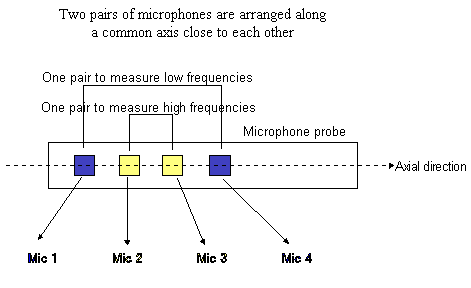
The sound intensity microphone is therefore used for sound source probing and for measuring sound power. Ono Sokki produces two types of sound intensity microphones - - a single-axis type (model MI-6410) in which two pairs of sound-pressure microphones are arranged close to each other in a straight line; and a three-dimensional type (model MI-6420) unique to Ono Sokki, in which four microphones are placed in each apex of a regular tetrahedron.
1-1. Single-axis Sound Intensity Probe (MI-6410 ![]() )
)
Structure
|
Principle
|
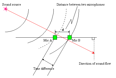
This method is also called the two-microphone method. The sound wavefront that reached microphone A (Mic A) will reach microphone B (Mic B) after a certain time difference. The difference in time is used to calculate the sound intensity component of the microphone axis and to judge the direction of sound as either backward or forward. Assuming the sound pressure at Mic A is p1(t) and that at Mic B is p2(t), then the average value of sound pressure P(t) and particle velocity V(t) are: Sound intensity can be determined by multiplying p (t) by v (t) and calculating the time average for this product, P(t)*V(t). |
Advantages
Frequencies in the range of 40 Hz to 10 kHz can be measured at once or simultaneously by arranging two pairs of probes, each pair having different frequency ranges along the same axis. The arrangement of two pairs of probes along the same axis effectively matches the acoustic centers so that errors are not generated when measurement is made. Less risk of poor contact and mechanical damage since the probes are of a single fixed structure. The small size and simple construction of the microphone cartridge (1/4-inch diameter) does not obstruct sound flow.
Dedicated microphone amplifiers and a sound-pressure phase-difference calibrator make the probes easy to use and produce highly accurate measurements.
Important Points
Measurement made once only gives one component of a sound vector.
In the vertical direction, the shortest distance from the effective acoustic center to the measuring object is 50 mm, so measurements cannot be made at points very close the probe.
The measuring frequency ranges of the two pairs of microphones are 40Hz to 1kHz and 400Hz to 10kHz respectively. It is therefore difficult to make measurements for intermediate ranges only ( i.e., from 200Hz to 5kHz ).
Applicable Standard : IEC-1043 Standard for sound intensity measuring equipment using two microphones.
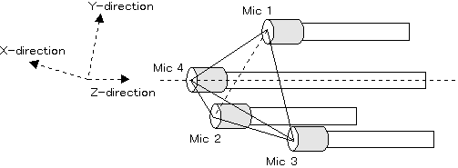
1-2. Three-dimensional Sound Intensity Probe (MI-6420 ![]() )
)
Structure
|
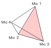 Construction in which four microphones are arranged in each apex of a regular tetrahedron. |
Principle
|
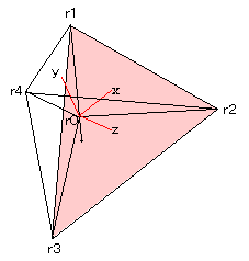
Four non-directive sound pressure microphones are arranged in the four apexes r1, r2, r3, and r4 of a regular tetrahedron. The center of gravity r0 of the regular tetrahedron is the effective acoustic center and x, y, and z axes when this center is taken as the origin are as shown in the figure. The algorithm for this method is considered to be an extension of the above method of using two-pairs of microphone. The two-pairs of microphones' method is applied to any two microphone pairs (six ways), in order to first determine the sound intensities in the directions of each pair, and then determine the three-dimensional sound intensities by calculating components along the X, Y, and Z axes of the microphone probe. |
Advantages
Three-dimensional sound intensity (three-directional components of sound vectors) can be determined by only one measurement using four microphones. The unique construction of the probe, in which four microphones are arranged in each apex of a regular tetrahedron, holds spatial symmetry and effectively matches the acoustic centers. It is difficult to obstruct the flow of sound by the arrangement of microphones, as the diameter of each is only 1/4 inch at the tip of thin shafts. This arrangement is specifically designed to ensure accuracy in measurement of sound of high frequencies.
Dedicated microphone amplifiers and a sound-pressure phase-difference calibrator make the probes easy to use and produce highly accurate measurements.
Important Points
A computation processor that can simultaneously process signals from four microphones is necessary for determining three-dimensional sound intensity.
A highest measurable frequency is 5 kHz (for 2 dB error).
Applicable Standard: There is no such standard at present.
2-1. What is a Sound Level Meter?
The sound level meter is a measuring instrument used to measure sound pressure level(LA, LP). The standards that apply are defined in JIS C1502 (IEC 651 Type 2), "Sound Level Meters" and JIS C1505 (IEC 651 Type 1), "Precision Sound Level Meters." In addition, There are integrating sound level meters that measure the percentile sound pressure level(LX) as a statistical quantity as well as integrated quantities, such as the equivalent continuous sound pressure level (Leq) and the single-shot sound exposure level(LAE).
Sound Level Meter and Precision Sound Level Meter
The purpose of the sound level meter (JIS C1502) is to measure environmental noise and for carrying out simple measurements at the sites. The purpose of the precision sound level meter is for use as an instrument that can be applied to sound studies in various fields or to any measurement conditions required by users who perform evaluation.
| JIS C1505 | JIS C1502 | |
|---|---|---|
| Frequency range | 20 to 12500 Hz | 20 to 8000 Hz |
| Instrumental error | 0.7 dB or less | 1.5 dB or less |
| Scale error | Error of 0.7 dB or less to the measuring range | Error of 1.5 dB or less to the measuring range |
2-2. Structure of Sound Level Meter
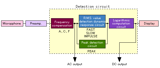
Microphone and Preamplifier
The microphone is a device that accurately catches sound and converts it into electrical signals and the preamplifier is a unit that amplifies the very weak signals picked-up to a certain level and converts the signal impedance. Since sound is a wave phenomenon in which air condensation and rarefaction disseminate sequentially, microphones and preamplifiers with high sensitivity and good frequency response are required to convert this air condensation and rarefaction to electrical signals proportionally. For microphones used for sound level meters, condenser type microphones are generally employed. Details of condenser type microphone are given in the preceding report .Frequency Compensation Circuit
This circuit is for carrying out weighting to electrical signals from the preamplifier in that frequency range. The commonly used types of weighting include:A-weighting of frequency
This weighting simulates the frequency response of human hearing. The characteristic of this type is that sensitivity decreases in the lower and higher ranges. This weighting is normally used in sound in sound level measurement.C-weighting of frequency
This weighting is based on a relatively flat frequency response and is used for recording AC outputs of the sound level meter or for measurements of impulsive sounds.F-weighting of frequency
This weighting gives a flat response over a wider range of frequencies than the C-weighting. It is used for frequency analysis of an object's sound.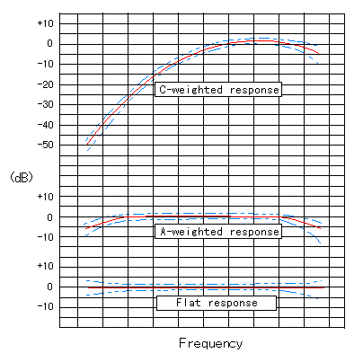
* Values between broken lines show tolerance.
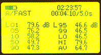
Dynamic Response (Time Weighting Circuit)
"Dynamic response" is a standard (in JIS C1505 or IEC651) for the movement of the indicator pointer (including digital display) used by the sound level meter for both fast responses (FAST) and slow responses (SLOW). The FAST response is approximately equal to the time response of the ear, while the SLOW response is for indicating the average amount of sound variation. The FAST response is normally used for the measurement of sound. In addition, some sound level meters having fast response are provided with an IMPULSE selector because the FAST selector cannot correctly measure the intensity of impulsive sound.AC Output and DC Output
The AC output terminal outputs electrical signals proportional to the degree of air condensation and rarefaction captured by a microphone. The DC output is a signal obtained by detecting AC output and converting it into a DC signal in dB through the dynamic response circuit and logarithmic computation circuit. The computation circuit corresponds to indicated values in dB of the sound level meter. For using a sound level meter as a sound sensor, the AC output is used. The AC output signal corresponds to sound pressure and has complicated waveforms composed of various frequency components. Effective countermeasures to noise can be taken if frequency components of the object noise are known. Thus, the AC output is utilized as an input signal to FFT (Fast Fourier Transform) analyzers or real-time (octave) analyzers, and DC output for recording on level recorders.Display
In the display, signal processing matches the DC output signal with a measuring level set up by the sound level meter and displayed as the sound level. The display shows the level in its analog form indicated by the deflection of the pointer, and also in its digital form as a numeric value and as well as its position on the bar indicator.
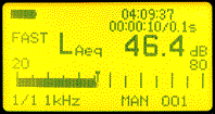
Equivalent continuous A-weighted sound pressure level
Percentile sound pressure level
2-3. Indicated Values with Sound Level Meters
Sound Pressure Level (LP, LA, LC)
In the field of noise, the sound pressure level is used as a practical scale for the amplitude of sound waves (sound pressure). It is measured in units of decibels (dB). To put it simply, sound waves of a high sound pressure level have a strong sound while sound waves of a low sound pressure level have a weak sound. It is expressed as a quantity based on human hearing (LA). With A-weighting applied to the sound pressure level, this level is used as a scale for noise intensity, and is also measured in units of decibels (dB).Equivalent Continuous Sound Pressure Level(Leq)
This measure can express fluctuating noise in a statistical and stable manner. The degree of noise and the length of time a man is exposed to it, is evaluated as an average value with time of the total noise energy over time, and indicated as a level. This level has been adopted as an environmental noise evaluation quantity in Japan since June 1998, and will become an important index for noise evaluation in the future.Single-shot Sound Exposure Level (LAE)
This is specified as a value for measuring noise of short duration generated once only (single shot) or intermittently. It becomes the value for sound level of steady-state sound if it continues for one second with an energy level equal to that of the total energy generated in a single-shot manner.Percentile Sound Pressure Level(LX)
For a long time, this value was used as a quantity for evaluating fluctuating noise and has been used as an evaluation quantity of noise in the Noise Regulation Law and the natural environment standards of Japan. If the sum of the periods in which the fluctuating noise level exceeds a certain level is equivalent to X% during a certain measuring period (t2-t1), then that sound level is called X percentile sound pressure level and is expressed as Lx.