
![]()
![]()
![]()
A laser Doppler vibrometer consists of an optical head that emits laser light and a converter that processes the Doppler frequency of the reflected laser light. The voltage signal from the converter is proportional to the velocity at which the object under measurement moves. This signal is input to an FFT analyzer or an alternative type of instrument to convert the signal into an acceleration or displacement signal. In addition, frequency analysis can be performed on the signal to examine and gain a better understanding of how the object behaves.
If an acoustic, radio or light wave of a specific frequency is beamed at a moving object, the frequency of the wave reflected from the moving object differs in proportion to the velocity of the object. This phenomenon is known as Doppler shift or the Doppler effect. The relationship between the frequency at which the wave is beamed and the frequency at which the wave echoes is outlined below.
1. If the object is approaching the source, the reflected frequency is higher than the emitted frequency.
2. If the object is receding from the source, the reflected frequency is lower than the emitted frequency.
The difference between the eitted frequency and the reflected frequency relates to the velocity of the moving object. Normally, the difference in frequency becomes larger as the velocity of the object increases.
The laser Doppler vibrometer is based on this principle. When laser light is beamed at a moving object, the frequency of the laser light reflected from the object differs from the original frequency of the emitted laser light due to this Doppler effect. The vibrometer considers the amount of Doppler shift generated. Given that the change in frequency isD, the velocity of the moving object is V, the wavelength of the emitted laser light is I, and the angle between the direction in which laser light runs and the direction in which the object moves is F, then the following equation holds true.
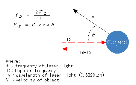
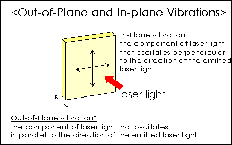
As shown in the fugure above, the frequency of the reflected laser light is f0+fD. Since the wavelength I used by the laser Doppler vibrometer is extremely stable, the Doppler frequency fD and velocity V are proportional. Normally, the angle F is set at 0 (only the component of reflected light parallel to incident light--out-of-plane vibration*--is detected) and, therefore, the velocity of the object moving in the direction of the emitted laser light can be determined by measuring fD. The frequency of laser light is so high, however, that it is extremely difficult to measure directly. For this reason, fD is normally determined by allowing the emitted laser light (f0) to interfere with the reflected laser light (f0+fD).
Types of Laser Doppler Vibrometers
Laser Doppler vibrometers can be classified according to their structural design as shown below. The model numbers shown are the vibrometers produced by Ono Sokki for each respective class.
| 1 | Vibrometers for out-of-plane vibrtion / Reference-beam vibrometers |
LV-1710 / LV-1720A |
| 2 | Vibrometer for three-dimensional vibration | LV-3300 |
The details of each type of vibrometer are given below.
These are the most basic laser Doppler vibrometers. The figure below illustrates how the LV-1710 and LV-1720A are configured.
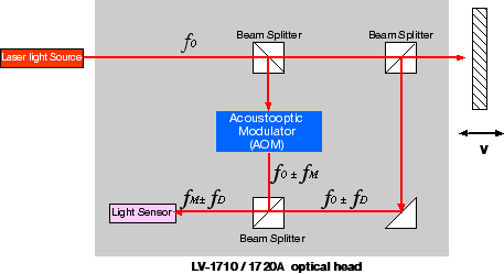
Laser light released from the light source is split into two beams, one of which serves as an incident beam directed at the object under measurement, while the other serves as a reference beam fed back within the vibrometer. The beam reflected from the object experiences Doppler shift in proportion to the vibratory velocity of the object. This beam is then made to interfere with the reference beam, which is given a frequency shift beforehand by the acoustooptic modulator, so that a beat frequency can be obtained. From this beat frequency signal, only the Doppler-shift component is singled out at the detector circuit and sent to the FM demodulator to be output as a voltage signal that is proportional to the vibratory velocity.
An object does not always vibrate in one direction only. It may in fact vibrate in a complex manner in three-dimensional directions. As products have become smaller in size and more precise, there has been an increasing need for measurement and analysis of three-dimensional, complex motion. The LV-3300 is a vibrometric system comprising three reference-beam laser Doppler vibrometer units. The system performs vector calculations when signals are received from these three vibrometers to simultaneously measure the X-, Y-, Z-axis vibratory velocity and the direction in which the object under measurement vibrates. The figure below illustrates how the optical heads of the LV-3300 system are configured and shows the equations for calculating the vectors.
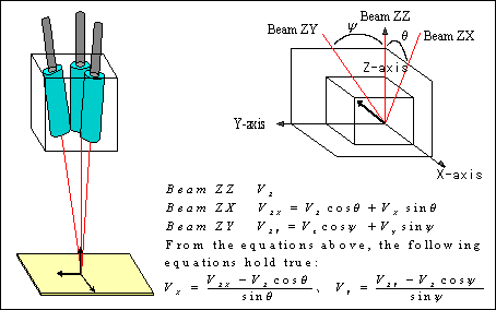
One of the three optical heads is arranged so that the dirction of its incident light coincides with the direction (Z-axis) in which the object moves; while the other two are arranged so that the directions of their incident light(ZX and ZY) are specific angles away from the Z-axis. Signals from these angled optical heads represent the vibratory velocities and vibrations in the ZX and ZY directions. Consequently, beams reflected from all three optical heads contain signal components for the Z, ZX and ZY directions in which the object vibrates. Thus, we can measure the vibratory characteristics of the object for the X-,Y- and Z-axis directions simultaneously, by inputting these three signals into a vector calculator.
Advantages of laser Doppler vibrometers, along with precautions
Advantages
· Non-contact measurement
· Wide dynamic range for measurement
· High spatial resolution
· Small sensor head
Precautions
· The sensor head must be placed directly opposite the object.
· The luminous energy of a reflected laser beam must be maintained at a given level.
· The vibrometer is susceptible to the effects of oil or water on an object.
· Extra care must be taken when measuring a rotating object since the vibrometer is affected by the noise caused by rough surfaces.
Supplementary Notes
1. Laser Doppler vibrometers do not affect the object under measurement due to their non-contact measurement method. The sensor head can be placed at a reasonable distance from the object (normally, 0.34 to 5m for the LV-1300, or more than 10m if combined with a commercially available lens). This feature enables us to measure even objects such as those that emit intense heat, without affecting the sensor head.Torsional vibration takes place as an object rotates. This type of vibration can occur for different reasons. In a rotational system where the drive unit and load section are directly coupled, such vibration is caused by a change in the revolution of the rotating part. In a multi-shaft system where gears, belts and chains are interconnected, such vibration is caused by a transfer error resulting from poor machining accuracy or a deformity in the power transmissions, or from a change in the revolution of the rotating parts. Normally, revolution changes, torsional vibration and transfer errors are intermingled in a complex manner. A variety of adverse effects develop in systems which experience these, such as:
1.Increase in vibration and/or noise
2.Deterioration in the positioning accuracy
3.Deterioration in the feed accuracy
4.Breakdown due to fatigue
Therefore, in a system comprising rotating parts and power transmissions, it is important to measure these three parameters--revolution change, torsional vibration and transmission error--in order to analyze the cause-and-effect relationship.
Changes in Revolution
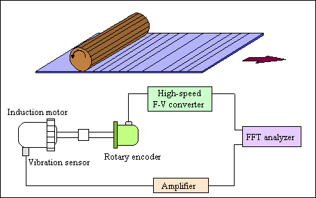
A change in revolution can be due to either an increase or decrease in the rotational angular velocity against the average angular velocity at a particular point on a rotating shaft. In this measurement, a high-resolution rotary encoder is used. The output signal from the encoder is converted from frequency to voltage (F-V) at high speeds, pulse by pulse, to deterimine the change in each revolution.
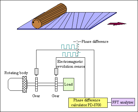
Torsional vibration represents changes in the relative angular displacement between two points on a rotating shaft. Normally, a pair of electromagnetic revolution sensors are used for this measurement. The vibrometer measures the torsion that develops across the driving and load sides of the shaft as the phase difference. The phase difference obtrained is F-V converted at high speeds and processed using frequency calculations to determine the torsional vibration.
Transission Errors
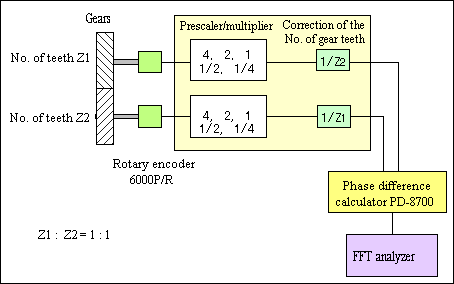
A transmission error is the lead or lag in the rotational angle at the front and back locations of a power transmission unit in a multi-shaft rotary machine. This is measured from the phase difference between the front and back locations of a power transmission, similar to the detection of torsional vibration noted earlier. The per-pitch transmission error is determined from the phase difference, and then processed by frequency calculations to determine the transmission error.
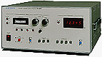
PD-8700 Torsional Angle Converter (Discontinue Product)
 |
Designed to execute 16-bit, precision digital computation and pulse-mode computation over four periods, this converter makes it possible to measure relative angular displacements at a resolution more than 16 times higher than conventional converters, for applications where phase differences between pulses are measured to determine torsional vibration, transfer errors in gears, and other variables. |
The following are cross-conversion equations used to find acceleration, velocity and displacement.
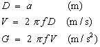 |
D Displacement V Velocity G Acceleration f frequency |
If frequency f is known and one of the variables D, V and G is measured, the other two physical quantities can be determined by calculation.
In the next issue of the ONO SOKKI TECHNICAL REPORT, we will discuss"sound and sensors".