Non-contact Thickness Meter
CL-5600 series
Electrostatic capacitance-type |
|
 |
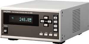
The CL-5600 Series non-contact thickness
meters use an electrostatic capacitance-type gap detector to measure
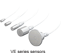
conductors, semiconductors and insulators. The VE Series
electrostatic capacitance-type gap detectors have shown proven
results as non-contact electrostatic capacitance-type sensors, and
enable high-accuracy, stable thickness measurement using easy
operations. The CL-5600 Series offers both a conductor/semiconductor
measurement function that uses two sensors (standard) and an
insulator measurement function (option: CL-0300) that uses one
sensor. Featuring a new outward appearance and enhanced functions,
they utilize the revamped electrostatic capacitance-type converters,
the VE Series gap detectors. The measurement range has been
expanded, and an easy-to-read fluorescent display has been utilized
for the display unit. Moreover, the separation of the gap converter
from the main unit enables the addition of an analog output, a
comparator function (option: CL-0100) and a high-resolution display
function (option: CL-0200) for even more flexibility and improved
ease of use. |
| |
|
 |
Features
-
The high-resolution calculation function enables a
resolution at 0.02μm by using VE-5010 with optional CL-0200.
-
The gap measurement range has been increased
considerably (Maximum 8 mm when VE-8020 is used.).
-
The length of the cable between the sensor and the gap
converter is 1.5 m.
-
The CL-5600S features separate gap converters (CL-0420).
The length of the cable between each gap converter and the main unit is 2.5
m as standard specification (Max. 10 m is possible on request as an
option.).
-
An easy-to-read vacuum fluorescent display has been
utilized at the display unit.
-
The RS-232C interface connection enables connection to a
printer.
-
Analog and comparator output functions are both provided
as optional CL-0100.
-
A function for measuring the thickness of conductors and
semiconductors is provided as standard, while a function for measuring the
thickness of insulators is provided as optional CL-0300.
Measurement methods
|
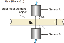
When measuring conductors or semiconductors |
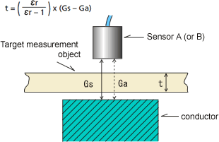
When measuring insulators (CL-0300 Insulator
measurement function) |
|
Install two sensors in parallel
within the measurement range for the target measurement
object. Specify the space (Gs) between these two sensors
at the CL-5600 Series. Insert the target measurement
object between sensors A and B and measure the gap
between each sensor and the target measurement object (Ga
and Gb) to obtain the thickness (t).
Note:
The sensor case and the material are assumed to have
equal potential. |
Specify the space (Gs) between the
sensor and the conductor (reference area) at the CL-5600
Series. When the target measurement object is inserted
between the sensor and the conductor (reference area),
the sensor output becomes Ga. The thickness (t) is
obtained from the amount of change in the sensor output
and the relative dielectric constant
εr.
εr.:
Dielectric constant (When the dielectric constant of a
vacuum is 1 the dielectric constant of the target
measurement object is referred to as the relative
dielectric constant.)
Note:
The sensor case and the material are assumed to have
equal potential. |
Object can be measured
|
Conductors, semiconductors (when using the CL-5600 or
CL-5600S’s standard functions) |
Insulators (when using the CL-0300 option’s
additional function) |
|
Metal, conductive materials such as
silicon wafers, double-sided copper-clad laminated
plates, pastes. Carbon plates. |
Thin objects that are composed of a
uniform, simple material throughout can be measured.
Relatively thin objects such as glass, crystal wafers,
sapphire wafers, film and plastic. |
Example of the
measurement
Specifications
| |
CL-5600 |
CL-5600S |
|
Measurement parameters |
Thickness of the conductor or
semiconductor that is under measurement |
|
Gap A between sensor A and the object under measurement |
|
Gap B between sensor B and the object under measurement |
|
Thickness of the insulator that is under measurement
(CL-0300 option)*1 |
|
Display modes |
ABS: Measured values |
|
DEVI: Deviation values (Measured
values ・reference values) |
|
Maximum, Minimum, Maximum ・Minimum |
|
Interface |
RS-232C (Cable: AX-5022/Sold
separately) |
|
SYNC function |
Possible for the cascade connection
with CL-5600 series |
|
Remote functions |
External start/stop of calculation
function, thickness calibration, etc. |
|
Gap converter |
・ |
CL-0420 (a 2.5-m length cable is
supplied as standard. ; can be optionally increased up
to a length of 10 m.) |
|
Measurable objects |
Conductors, semiconductors, insulators
*1 |
|
Display parameters |
Thickness, Gap A, Gap B |
|
Resolution |
Depends on which sensors are used.
0.1, 0.5, 1, 2 μm
(0.02, 0.05, 0.2, 0.5, 1μm by using optional CL-0200 *2)
The display
resolution and linearity when used in combination with
the VE Series electrostatic capacitance-type gap
detectors are as follows.
|
Sensor type |
Measurement
range (μm) |
Display
resolution (μm) |
Linearity(%/F.S.) |
| VE-5010*1 |
0 to 200 |
0.1(0.02)* |
0.15(0.12)* |
| VE-5010 |
0 to 500 |
0.1(0.05)* |
0.15(0.12)* |
| VE-1020 |
0 to 1000 |
0.1(0.1)* |
0.15(0.12)* |
| VE-1520 |
0 to 1500 |
0.5(0.2)* |
0.15(0.12)* |
| VE-3020 |
0 to 3000 |
1(0.5)* |
0.15(0.12)* |
| VE-8020 |
0 to 8000 |
2(1)* |
0.15(0.13)* |
|
Sensor type |
Measurement
range (μm) |
Display
resolution (μm) |
Linearity(%/F.S.) |
|
VE-2011 |
20 to 200 |
0.1(0.02)* |
0.15(0.12)* |
|
VE-5011 |
50 to 500 |
0.1(0.05)* |
0.15(0.12)* |
| VE-1021 |
100
to 1000 |
0.1(0.1)* |
0.15(0.12)* |
VE-3021
(Discontinued) |
300
to 3000 |
1(0.5)* |
0.15(0.12)* |
| VE-8021 |
800
to 8000 |
2(1)* |
0.15(0.13)* |
*(): When using
CL-0200 High-resolution calculation function (option) |
|
Sampling time |
20 ms |
|
Averaging |
Moving mean, 1 to 64 times |
|
Display |
Vacuum fluorescent display; either
2-row display or 1-row display (large character size)
can be selected. |
|
Comparator function (Option: CL-0100 *3) |
3-CH output |
|
Analog output (Option: CL-0100 *3) |
Thickness, Gap A, B (linearity ±0.2%
F.S./10% to 100% F.S.) |
|
Compatible printer (option) |
DPU-414 (Connection cable is provided
as standard part.)
* AC Power supply adaptor: PW7007 series (Sold as an
option) |
|
Power requirement |
100 to 240 VAC, 50/60 Hz |
|
Operating temperature range (achieving
the specified accuracy) |
+21 to +25°C |
|
Operating temperature range |
0 to +40°C |
|
Operating humidity range |
20 to 80 %RH |
|
External dimensions, weight |
210(W) mm x 99 (H) mm x 276(D) mm, 4.5
kg |
210(W) mm x 99 (H) mm x 276(D) mm, 4.5
kg CL-0420: 42(W) mm x 56 (H) mm x 120 (D) mm, 0.6 kg |
|
*1: CL-0300 Insulator measurement
function (option)
*2: CL-0200 High-resolution function (option)
*3: CL-0100 Output function (option) |
n CL-0100 Comparator output (terminal block)
The items for comparison and the
threshold can be set respectively for each of the three
comparator channels (COMP1/COMP2/COMP3). The comparator
operates as shown in the figure below.
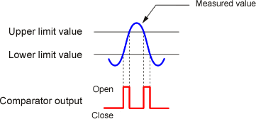
The comparator contact output closes when the
specified upper limit value (UPPER) is less than the
specified value or when the specified lower limit value
(LOWER) is larger than the specified value. |
n VE Series
electrostatic capacitance-type gap detectors
Standard type
|
Model name |
VE-5010 |
VE-1020 |
VE-1520 |
VE-3020 |
VE-8020 |
|
Measurement range (μm) *1 |
0 to
500 |
0 to
1000 |
0 to
1500 |
0 to
3000 |
0 to
8000 |
|
Minimum diameter of target (mm) *2 |
φ6 |
φ8 |
φ10 |
φ20 |
φ40 |
|
Cable length (m) |
1.5 (attached cable as standard) |
1.5 (VL-1520 as sold separately) |
|
Temperature function |
k1 = 1.7 x 10⁻⁵, k2 =
3.4 x 10⁻⁵ |
|
Operating temperature range *3 |
0 to +80°C |
Clamp-shape type (common to Φ10mm)
|
Model name |
VE-2011 |
VE-5011 |
VE-1021 |
VE-3021
(Discontinued) |
VE-8021 |
|
Measurement range (μm) *1 |
20 to
200 |
50 to
500 |
1000
to 1000 |
3000 to
3000 |
8000 to
8000 |
|
Outer dimensionst (mm) *2 |
φ3 |
φ6 |
φ8 |
φ20 |
φ40 |
|
Cable length (m) |
1.5 (VL-1520/1521 as sold separately) |
|
Temperature function |
k1 = 1.7 x 10⁻⁵, k2 =
3.4 x 10⁻⁵ |
|
Operating temperature range *3 |
0 to +80°C |
|
Note: The VL-1520 signal cable is sold
separately.
Note:
*1: The measurement range refers to the maximum gap
between the surface of the sensor tip and the object
under measurement.
*2: The surface measurement area of the object under
measurement must be larger than the external diameter of
the sensor.
*3: The operating temperature range is the temperature
range in which the sensor can operate, not the operating
range for which accuracy is
guaranteed. The operating range for which
accuracy is guaranteed at 23±2°C. The temperature
characteristics of the VE series are shown in
the formula below. |
|
 |
Revised: 2009/07/31
|


