Panel switch operation and function list

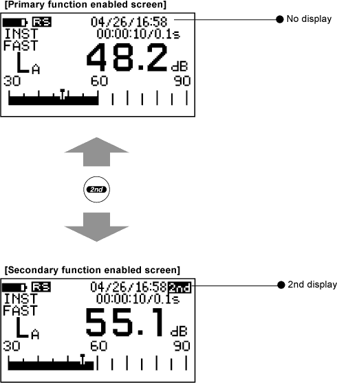
1. Switching the function switch (Pay attention to 2nd button)

The panel switch performs two kinds of operations, function switch (primary and secondary) and combination switch, which is operated when two different switches are pressed at the same time. Function switch has a primary function and secondary function, and those are switched each time you press the panel switch [2nd]. When the primary function is selected, the function inscribed at the top of each switch is enabled. When the secondary function is selected, the function printed in italic above each switch is enabled (Displayed in blue). When the secondary switch functions are enabled, the "2nd" mark appears at the top right of the screen.


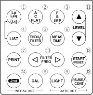
2. List of primary function panel switch


1 Lp/Leq/…(Lx)

Switches between display measurement items.

(Lx value cannot be displayed in normal measurement screen.)

2 A/C/FLAT

Switches the frequency compensation characteristics in the following order.

A>C>FLAT>A>C…

3 F/S/IMP

Switches the dynamic characteristics in the following order.

FAST>SLOW>IMPULSE>10 ms>FAST…

4 LIST

Switches between the standard (graph) mode and list mode screens.

(Lx values cannot be displayed while calculating.)

During real-time octave data measurement, this switch is used to switch between the graphic and list modes.

*5 THRU/FILTER

Switches the type of the octave filter to be used.

6 MEAS TIME

Switches the calculation execution time in the following order.

FREE>1s>3s>5s>10s>20s>30s>1m>3m>4m10s>5m>10m>

15m>30m>1h>8h>24h>FREE…

7 PRINT

Prints measured values.

(Example of printing with the digital printer RQ-110. For details, see the RS-232C manual.)

During LX value calculation: Lp values are printed only when the sampling interval is set to 5s.

During calculation data display: Calculation result data except for Lx and the data and time are printed.

During list display: All pages which can be displayed in list form and the date and time are printed.

During Lp value display: Lp values and the date and time are printed.

8 CAL

Turns ON or OFF the calibration mode.

(It cannot be operated during filter ON setting and real-time octave data measurement.)

9 LIGHT Turns the back light ON or OFF.
*10 FILTER FREQ

Switches the center frequency of the filter in the following order.

1/1 octave: 31.5>63>125>250>500>1k>2k>4k>8k>31.5…

1/3 octave: 20>25>31.5>40>50>63>80>100>125>160>200>250>315>400>500>
630>800>1k>1.25k>1.6k>2k>2.5k>3.15k>4k>5k>6.3k>8k>10k>

12.5k>20...

11

LEVEL
()

Switches the level range.
12 START (RESET) Starts calculation. (Previous calculation results are reset.)
13 PAUSE/CONT

During calculation: Pause the calculation.

During pause of calculation: Restarts the calculation.

14 2nd Switches between the primary and secondary switch functions.
 
*: To use this function, an option is required. Select it according to the application or purpose.


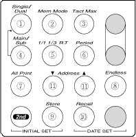
3. List of secondary function panel switch


1 Single/Dual

Switches between the single and dual calculation modes.

2 Mem Mode

Switches the memory mode in the following order.

OFF>MAN>FSCAN>AUTO>AUTO Lx>Lp>OFF…

3 Tact Max

Switches between the instantaneous value (INST) and maximum-value-per second (TMAX) modes.

4 Main/Sub

Switches between the main and sub screen at the time of dual mode calculation.

5 1/1, 1/3, R.T

Switches between the 1/1 and 1/3 octave modes.

(Effective only when the 1/1 or 1/3 octave filter is attached.)

6 Period

Switches the sampling interval in the following order.

When storing data in the Lp memory:

5ms>10ms>20ms>50ms>0.1s>0.2s>1s>2s>5s>5ms…

During Lx measurement: 10ms>0.1s>0.5s>1s>5s>10ms…

7 All Print

Prints data stored in memory at one time.

(For detail, refer to the "RS-232C manual".)

8 Endless

Continues the calculation.

(Calculation is stopped if calculation stop operation is made.)

9 Store Starts store operation. (Used to start scanning of Lp record and filter.)
10 Recall

Recalls stored data. (Call the stored data)

11

Address
()

Switches the memory address.
 

* To use this function, an option is required. Select it according to the application or purpose.

* Optional function for the LA-2111. To use this function, an option is required.


4. Function and operation of combination switch

Combination switch is the switch which operates when two panel switches are pressed at the same time. These switches are used to cancel panel conditions, display the calendar setting screen and clear the memory.


Canceling the panel conditions (INITIAL SET)

When the power is turned ON while pressing the panel switches [2nd] and [CAL], the panel condition function is canceled and the Sound Level Meter is activated with initial conditions. For these two switches, [INITIAL SET] is printed.


Displaying the calendar setting screen (DATE SET)

When the power is turned ON while pressing the panel switches [LIGHT] and [PAUSE/CONT], the built-in software version, installation conditions of options for the main unit, and screen for calendar setting are displayed. For these switches, [DATE SET] is indicated.


Clearing the memory

When the power is turned ON while pressing the panel switch [FILTER FREQ], all memories are cleared. The memory to be cleared cannot be selected.

Revised:2001.10.12


webinfo


© Copyright. ONO SOKKI CO., LTD. All Rights Reserved. | Terms of use | Privacy policy