![]()
![]()
![]()


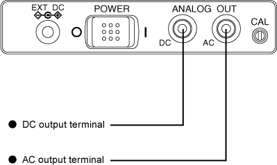
AC/DC output setting
AC and DC signals are outputted from the AC and DC output terminals of the ANALOG OUT terminal.
AC and DC output terminals can be connected to the level recorder, real-time analyzer or other equipment.
[Notes]
• Both AC and DC output terminals have an output resistance of 50 Ω±2%, however, none of them can drive 50 Ω terminating resistance. Be sure to connect to a measuring unit with an input impedance of 10 kΩ or more.
• Therefore, be sure to complete calibration together with the equipment to be connected before use.
|
AC output
After frequency correction was performed by analog processing, the following signal is output from the AC output terminal. The specification of the signal is as follows.
Output level of upper limit of the level range display |
0.707 Vrms ± 15% |
|---|---|
Offset voltage |
±10 mV or less |
Therefore, if the steady sine wave signal with the upper limit of the level range display is supplied, the signal from the AC output terminal is as follows;
±1 V = 0.707 Vrms = -3 dBv
If the input level of the steady sine wave signal is adB larger or smaller than the upper limit of level range display, the signal from the AC output terminal is as follows;
0.707 × 10a/20 Vrms = -3 + a dBv
For example, if the measurement level is -20 dB smaller than the upper limit of level range display (equivalent to 90 dB when the level range is 40 dB to 110 dB), the output signal is as follows;
0.707 × 10(-20)/20 = 70.7 mVrms = -23 dB
The internal calibration signal is -6 dB smaller than the upper limit of level range display. Therefore, the AC output voltage is 354 mVrms or -9 dBv (equivalent to 104 dB when the level range is 40 dB to 110 dB). When the AC output level at the time of signal input is bVrms or adBv, the indication value on the screen is separated from the upper limit of level range display as follows;
20 × LOG 10(b/0.707)dB or a + 3 dB
For example, when the AC output is 100 mVrms = -20 dBv, the indication value is separated from the full scale as follows;
20 × LOG 10(0.1 Vrms/0.707)dB = -20 dBv + 3 dB - 17 dB
This is equivalent to 93 dB with a level range display from 40 dB to 110 dB. The maximum output level of the AC output is 0.707 Vrms, and the linearity is guaranteed for up to this level.
DC output
The DC output is output through the D/A converter as a signal corresponding to almost the same level as the bar indicator. (Please refer to the following specifications.) The bar indicator is updated at 100 ms intervals and the output of the D/A converter is updated at an interval of approx. 8.2 ms. The DC output can be applied to sudden level variation.
Output level of upper limit of the level range display |
2.5 V ± 150 mV |
|---|---|
Scale factor |
0.5 V ± 18 mV/10dB |
Therefore, if a steady sine wave with the upper limit of level range display is input, the DC output is 2.5 V. The scale factor is 0.5 V/10 dB. If the input level of the steady sine wave signal is adB larger or smaller than the upper limit of the level range display, the DC output is represented by the following expression.
2.5 + 0.5 × a/10 V
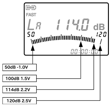
For example, if the measurement level is -20 dB smaller than the upper limit of level range display (equivalent to 9 dB when the level range is from 40 dB to 110 dB), the DC output is;
2.5 + 0.5 × -20/10 = 1.5 V
The internal calibration signal is -6 dB smaller than the upper limit of level range display. Therefore, the DC output is (Equivalent to 104 dB when the level range is from 40 dB to 110 dB.);
2.5 + 0.5 × -6/10 = 2.2 V
When the DC output is dV, the indication value on the screen is separated from the upper limit of level range display by;
(b - 2.5)/0.5 × 10 dB
For example, when the DC output is 1.65 V, the indication value is separated from the upper limit of level range display by (Equivalent to 93 dB when the level range is from 40 dB to 110 dB.);
(1.65-2.5)/0.5×10 = -17 dB
The maximum output level of the DC output is 3 V. This level is the same as the level of the sine wave with an indication value which is 10 dB larger than the upper limit of level range display. When the steady signal exceeds this level, OVER is displayed.
|
Revised:2002.01.09