
![]()
![]()
![]()


This is an explanation of the timing chart of the BCD connector input signal. For the pin arrangement of the BCD connector, please refer to "The explanation of the BCD OUT connector signal of the DG-4120 Digital Gauge Counter."
Timing chart of HOLD input, BUSY input and print command output
When the data is taken into the external device such as a PLC, input the HOLD signal to make the BCD signal condition stable. When the data is taken into the external device without inputting the HOLD signal, the data cannot be captured correctly.
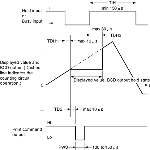
THDH1
Time from hold signal input to data hold displayed value and BCD output data is maximum 10 µs.
TDH2
Time from the release of the hold signal to the release of the hold state is maximum 30 µs.
TDS
Time from the holding of the displayed value and the BCD output to print command signal output is maximum 10 µs.
PWS
Print command signal pulse widths are 100 to 150 µs.
TIH
The interval time from the release of the hold signal to the input of the signal again is minimum 150 µs. If the hold signal input intervals are shorter than 150 µs, the print command signal may not be output.
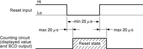
Reset signal timing chart
The reset input signal must have a pulse width of 20 µs or more. It takes up to 20 µs from reset signal input to reset state. It also takes up to 20 µs from the release of the reset signal to the release of the reset signal state.
Print command output timing chart
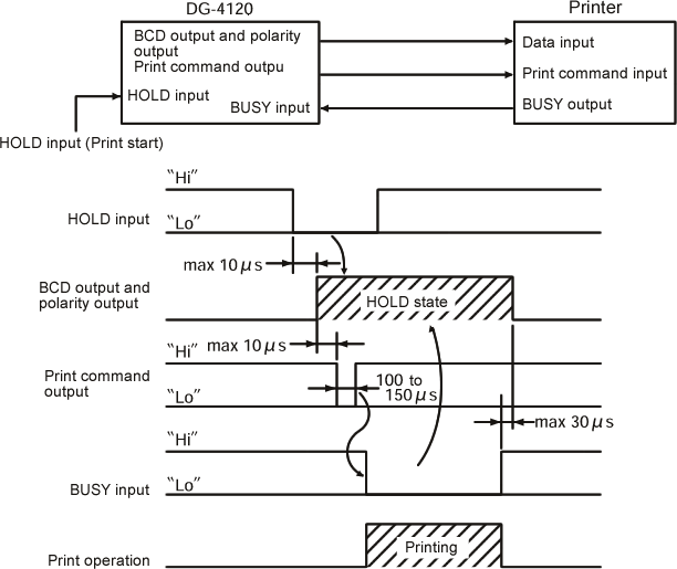
In the figure shown as above, the printer is started at rising of the print command pulse signal. The hold input must be maintained at Low level until the BUSY input turns into Low level. Please input the signal which shows the printer is in operation. The signal will be ignored, even if the HOLD signal is inputted during the printing.
Revised:2000.12.08
