No.5 Measurement of frequency response function using sine sweep signals
In this column, I will talk about the measurement of frequency response function using sweep signals, etc.
To measure the natural vibration frequency, there is a method of vibrating the object with an exciter and obtaining the frequency response function, or measuring the frequency response function of filters.
This time, I will introduce about the measurement of the frequency response function using the sine sweep signals output from the signal output module built into an FFT analyzer. There are two measurement methods, the FFT and the FRA method. I will introduce the FFT method here.
●Overview of measuring frequency response function using sine sweep signals
The figure 1 shows the system configuration example for outputting sine sweep signals from the signal output module built into an FFT analyzer and measuring the frequency response function:
-The built-in signal output module of the DS-3000 series outputs the sine wave with a certain frequency.
-Performing FFT analysis for the signal output from CH1 and the response signal of the CR circuit from CH2 to obtain the frequency response function.
-While changing the frequency, the above operation is automatically repeated and the frequency response function for the necessary band is measured.
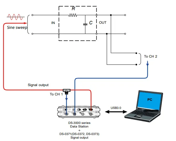
Fig.1 System configuration example
●Time for measuring the frequency response function using sine sweep signals
It is necessary to perform FFT analysis once or the average number of times to measure a certain frequency. The data for time length of FFT is required, and the FFT time length can be obtained from frequency range and sampling points as follows.
Number of lines= Sampling points ÷ 2.56
Frequency resolution [Hz]= Frequency range [Hz] ÷ Number of lines
Time length (sec)= 1 ÷ Frequency resolution [Hz]
For example, when frequency range: 1 kHz, sampling points: 1024, number of lines: 400, the frequency resolution is 2.5 Hz, and the time length is 0.4 seconds. The theoretical value of the measurement time for frequency response function is determined by the following equation.
Number of FFT calculation = (Stop Frequency [Hz] – Start Frequency [Hz] ÷ Frequency resolution +1
Measurement time (average once) =FFT time length [sec] x Number of FFT calculation
Measurement time (multiple times) =Measurement time (average once) x { 1 + (1- overlap amount [%] ÷ 100) x(Number of averages -1)}
The measurement time obtained by the above equation is a theoretical value. Actually, it takes 10 to 20 % more time than since there is a slight time lag between the end of FFT calculation at a certain frequency and switching to the next frequency.
When measuring frequency response function from 100 Hz to 500 Hz, 161 times of FFT calculation {(500 - 100)/ 2.5 + 1} = is required. If averaging once, the time length will be 64.4 seconds (=161 x 0.4 sec). If averaging 4 times, overlap amount, 66.7%, the time length, the time length will be 128.8 seconds ≒64.4 x{ 1+(1-66.7/100) x 3}.
Finer the frequency step is, longer the measurement time is. If the frequency step is half, the measurement time will be 4 times as the time length is 2 times and the number of FFT calculation is 2 times.
If the measurement is performed under the initial setting value of analyzer for frequency range, sampling points and number of averaging count, the measurement time may be extremely longer. Check if the measurement time is too long using the above equation, reduce sampling points or make frequency resolution rough before the measurement.
●Changing the frequency of sine wave and measuring frequency response function
Figure 2-1 shows an example of changing frequency of sine wave and the timing of FFT calculation when the number of averaging count is once. In this example, the frequency step (frequency resolution) is 1 Hz, thus one time FFT calculation requires one second of data. First, the since wave with 1 Hz is output, FFT is performed to obtain the frequency response function of 1 Hz component. Then, repeat FFT with different frequencies like 2, 3 Hz and so on.
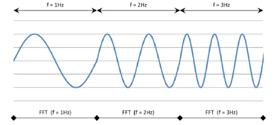
Fig. 2-1 Timing of FFT calculation (averaging count: 1)
Figure 2-2 shows an example of switching frequency of sine wave and the timing of FFT calculation when the number of averaging count is 4 times and the overlap amount is 66.7%. The first FFT is performed when the 2 Hz of sine wave starts to output. Since the amount of overlap is 66. 7 %, the second FFT is performed after 0. 33 seconds. In this way, the FFT is automatically performed every 0. 33 seconds.
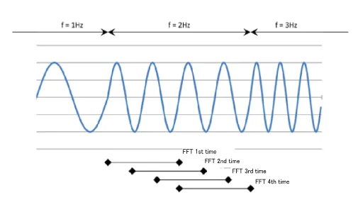
Fig. 2-2 Timing of FFT calculation (averaging count: 4, overlap: 66.7%)
[Input/ Output setting]
●Configuration setting
Make sure that the channels used for measurement turn "ON".
Note that you cannot change the channel settings used in the graph or other.
●Cross operation CH setting
Confirm if the channels for measuring the frequency response function are registered.
●Frequency range
Set the frequency range.
●Input setting
Turn off the “Auto-range”. Adjust the voltage range according to the magnitude of the input signal. If the input over occurs even once during measurement, increase the voltage range.
Set the coupling to "AC".
If you are connecting a sensor that requires a constant current power supply, such as an accelerometer or microphone, set CCLD to “ON”.
●Sampling condition setting
Set to “Internal” and set “Overlap amount”, “Sampling points”.
●Unit calibration
Set according to the signal or sensor connected to each channel.
●Window function setting
Set to “Rectangular”.
●Averaging processing setting
Set to “Power SP sweep”.
Set Averaging condition to “Count”, and set “Averaging count”.
Turn on “Sweep synchronized with signal output”.
●Signal output setting
Set the “Sing Output Mode Setting” to “Sweep Ave Sig Output”. Set the start frequency, stop frequency, amplitude and DC offset in the unit of “V”.
Display graphs such as Time-axis waveform, the power spectrum, frequency response function, coherence function accordingly. In addition, set the X-axis and Y-axis scales appropriately.
●Summary
This time, I’ve introduced how to measure the frequency response function using sine sweep signals output from a signal output module built into an FFT analyzer. Next time, I will introduce to measure using sine sweep signals output from an external device.
(Y·K)