No.28 Time constant and leveling
"Time constant" is one of the setting parameters when measuring the level of sound or vibration with a sound level meter or vibration level meter, or when performing Real-time Octave Analysis (RTA analysis) with analysis equipment.
Since the instantaneous waveform of sound and vibration is a waveform that quickly waves up down (plus or minus), the magnitude of the sound or vibration cannot be measured from the instantaneous waveform itself. When measuring the magnitude of sound or vibration, it is obtained by converting to the "RMS (root mean square value)" from the instantaneous waveform, and converting the "RMS" to the decibel values as leveled.
There are some methods to obtain the “RMS” from instantaneous waveform, the RMS detection dynamic characteristic circuit is the one of method. “Time constant” is one of parameters which determine the characteristics of this circuit.
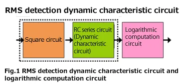
RMS detection dynamic characteristic circuit and logarithmic computation circuit
Figure 1 shows the block diagram of process for the sound level meter that RMS value is obtained from the instantaneous waveform using the RMS detection dynamic characteristic circuit and converted to the decibel value (leveled). When the time waveform of sound or signal is squared and passed through RC series circuit, the RMS value can be obtained. By inputting into logarithmic computation circuit, the RMS value is converted to the decibel values as leveled in the Figure 1.
Assume that the same processing as this circuit is performed on the time-series data sampled by the A/D converter. The instantaneous waveform sampled by an A/D converter is x(i). The output y(i) of the RC series circuit (dynamic characteristic circuit) can be obtained from Equation 1. This is the result of weighting the output y(i -1) and the square value of the instantaneous waveform x(i)2, then adding them together. The sound level L(i) of time i can be obtained from Equation 2. Since the unit of y(i) is Pa2, when calculating by taking the square root, it becomes Equation 2’. The calculation result of Equation 2 and 2’ is same.
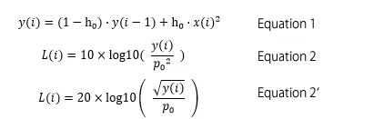
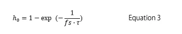
Here, τ is the time constant (s), fs is the sampling frequency (Hz), and p0 is the reference value of acoustic pressure, 20 μPa. h0 is a constant defined by Equation 3. When the time constant is 125 ms and the sampling frequency is 48 kHz, h0 is a small value such as approximately 0.0001667.
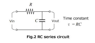
RC series circuit and its output
RMS detection dynamic characteristic circuit is based on RC series circuit, and which resistance(R) and capacitor (C) are connected in series (Fig.2). Here, τ = RC is a value called the time constant of this circuit.
When one cycle of the rectangular wave pulse is input into RC series circuit, the response waveform of RC series circuit is shown in Figure 3. In the time constant τ seconds after the pulse is input, it becomes approximately 0.63 and towards to exponential “1”. In the time constant τ seconds when the pulse breaks, it becomes approximately 0.37 and towards to exponential “0”.
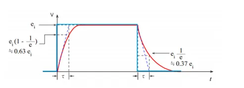
Fig.3 The rectangular wave pulse (blue) vs the response waveform of RC series circuit (red)
The burst signal and its sound pressure level
The burst signal (duration 1 second, frequency 1 kHz, half amplitude 1. 41 Pa) and its sound pressure level are shown in Figure 4. The upper is instantaneous sound pressure waveform, the middle is output of dynamic characteristic circuit (square of sound pressure), and lower is sound pressure level (dB). Time constant is F (125 ms).
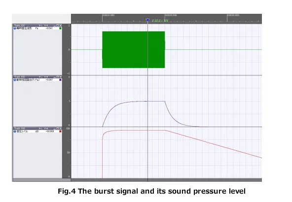
The output of the dynamic characteristic circuit is almost zero (0.0183 Pa2) in about 0.5 seconds after the burst signal stops, while the sound pressure level is only 17.37 dB down. These are the only differences between seeing as the sound pressure square value and decibel value. The sound pressure level after the burst signal stops is decreasing with a slope of approximately 4. 34 dB every 125 ms. It decreases about 34.74 dB in per 1 second.
Table 1 shows the values every 0.0625 seconds for the waveform in Figure 4. A sine wave with half amplitude of 1.41 Pa is added. As you compare with Fig. 3, the circuit output reaches 0.6320 Pa2 (91. 99 dB) in 125 ms (time constant) after the burst signal is input. In 500 ms (time constant), it reaches 0.9815 Pa2 (93.90 dB), which is almost same level as the signal sound pressure level (94 dB). After the burst signal stops, the circuit output (Pa2) is decreasing at a slope (rate) of 0.3677 times every 125 ms (time constant). If this is expressed in sound pressure level (dB), it is decreasing by 4.34 dB every 125 ms (time constant).
Table 1. The burst signal and its sound pressure level
| Time(s) | Amplitude(Pa) | Circuit output(Pa2) | Sound pressure level(dB) | Attenuation(dB) |
|---|---|---|---|---|
| 0.8750 | 0 | 0 | - | - |
| 0.9375 | 0 | 0 | - | - |
| 1.0000 | 1.41 | 0.0000 | - | - |
| 1.0625 | 1.41 | 0.3934 | 89.93 | - |
| 1.1250 | 1.41 | 0.6320 | 91.99 | - |
| 1.1875 | 1.41 | 0.7767 | 92.88 | - |
| 1.2500 | 1.41 | 0.8645 | 93.35 | - |
| 1.3125 | 1.41 | 0.9178 | 93.61 | - |
| 1.3750 | 1.41 | 0.9501 | 93.76 | - |
| 1.4375 | 1.41 | 0.9697 | 93.85 | - |
| 1.5000 | 1.41 | 0.9815 | 93.90 | - |
| 1.5625 | 1.41 | 0.9887 | 93.93 | - |
| 1.6250 | 1.41 | 0.9931 | 93.95 | - |
| 1.6875 | 1.41 | 0.9958 | 93.96 | - |
| 1.7500 | 1.41 | 0.9974 | 93.97 | - |
| 1.8125 | 1.41 | 0.9983 | 93.97 | - |
| 1.8750 | 1.41 | 0.9989 | 93.97 | - |
| 1.9375 | 1.41 | 0.9993 | 93.98 | - |
| 2.0000 | 0 | 0.9995 | 93.98 | 0.00 |
| 2.0625 | 0 | 0.6062 | 91.81 | 2.17 |
| 2.1250 | 0 | 0.3677 | 89.63 | 4.34 |
| 2.1875 | 0 | 0.2230 | 87.46 | 6.51 |
| 2.2500 | 0 | 0.1353 | 85.29 | 8.69 |
| 2.3125 | 0 | 0.0820 | 83.12 | 10.86 |
| 2.3750 | 0 | 0.0498 | 80.95 | 13.03 |
| 2.4375 | 0 | 0.0302 | 78.78 | 15.20 |
| 2.5000 | 0 | 0.0183 | 76.61 | 17.37 |
| 2.5625 | 0 | 0.0111 | 74.43 | 19.54 |
| 2.6250 | 0 | 0.0067 | 72.26 | 21.71 |
| 2.6875 | 0 | 0.0041 | 70.09 | 23.89 |
| 2.7500 | 0 | 0.0025 | 67.92 | 26.06 |
| 2.8125 | 0 | 0.0015 | 65.75 | 28.23 |
| 2.8750 | 0 | 0.0009 | 63.58 | 30.40 |
| 2.9375 | 0 | 0.0006 | 61.41 | 32.57 |
| 3.0000 | 0 | 0.0003 | 59.23 | 34.74 |
| 3.0625 | 0 | 0.0002 | 57.06 | 36.92 |
| 3.1250 | 0 | 0.0001 | 54.89 | 39.09 |
| 3.1875 | 0 | 0.0001 | 52.72 | 41.26 |
| 3.2500 | 0 | 0.0000 | 50.55 | 43.43 |
| 3.3125 | 0 | 0.0000 | 48.38 | 45.60 |
| 3.3750 | 0 | 0.0000 | 46.20 | 47.77 |
| 3.4375 | 0 | 0.0000 | 44.03 | 49.94 |
| 3.5000 | 0 | 0.0000 | 41.86 | 52.12 |
Summary
When rectangular pulse is input to the RC series circuit, the output reaches approximately 0.63 times of the amplitude pulse in the same time as the circuit time constant. When the pulse ends, the output of the circuit decreases at a slope (rate) of approximately 0.37 times in the same time as the time constant.
Since the RMS detection dynamic characteristic circuit of sound level meter uses the same circuit, the same characteristic is shown. When expressed in the sound pressure square value (Pa2), it will decrease by 0. 37 times in the same time as the time constant, so it becomes very small immediately. While, when expressed in acoustic pressure level (dB), it will only decrease by 4. 34 dB in the same time as the time constant.
When the burst signal or pulses sound stops, the sound pressure level doesn’t decrease immediately due to the effect of time constant. If time constant is 125 ms, it decreases to 34.74 dB in 1 second. In order to accurately measure the sound pressure for each pulse sound which repeatedly generates, it is necessary to set the pulse sound interval between 0.5 seconds and 1 second. If the time constant can be changed to a short time constant, for example, if the time constant is set to 10 ms, it will decrease by 4.34 dB at 10 ms, it will not be affected by short interval of sound.
(YK)