No.27 Connection of the open collector output with PLC
When the pulse signal output of Rotary encoder is the open collector, we have a few queries how to connect with the counter unit of PLC or tachometer.
Here we explain mainly about the current flow.
If it is voltage signal, you have in mind to connect to the PLC input (+, -). However, if it is the open collector, you’re not sure how to connect…
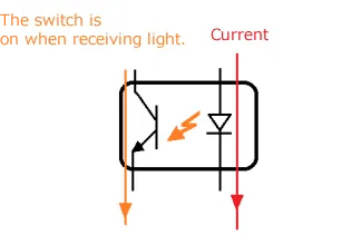
Here’s an idea, which you may consider the open collector as ON/OFF switch.
The current flows when the switch is ON, while it stops when the switch is OFF. This means the signal is changing when ON or OFF. Then, it is important to connect the current in the correct direction.
Since the open collector cannot output voltage by itself, an external power supply is required to send current. There are 2 types of the output of open collector. We recommend NPN transistor type (sync type). It is necessary to connect so that current flows into the collector terminal. Once the current flows, PLC receives the signal as ON.
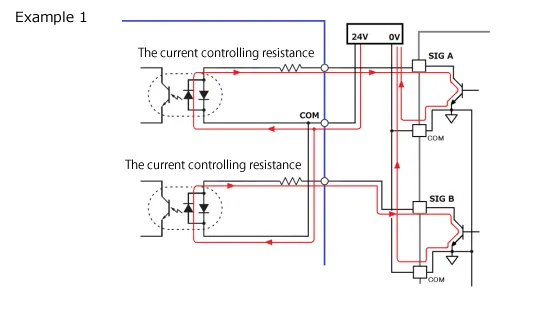
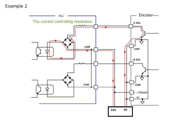
The figure below is an example of Receiver (PLC).
Please connect according to the operation manuals for encoder or PLC.
Basically it is important to connect in consideration of the current flow direction and the flow path.
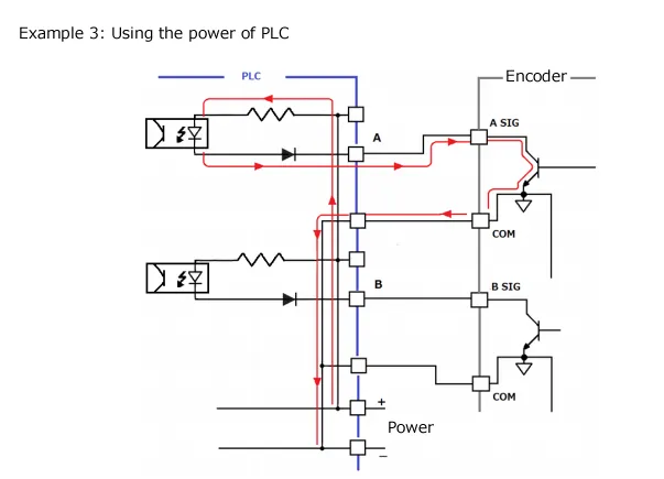
As for the power supply to flow the current, the power provided by PLC can be used.
The reference
Photocoupler:
It is a combination of LED that emits when current flows and phototransistor that conducts when receiving light. Since the switch is turned on and off with light, the input and output can be electrically isolated.
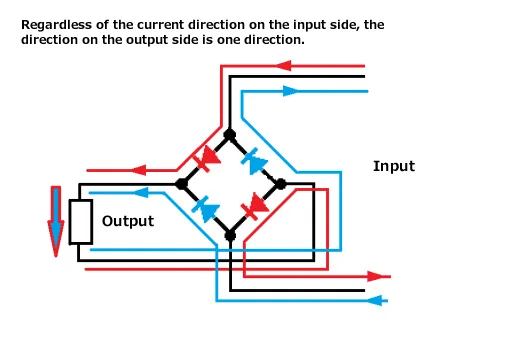
It is also used as a circuit that takes the absolute value of AC signal changing to +/-.
(H.K)