No.21 Calibration of Accelerometer using with Vibration calibrator
When analyzing acceleration signals recorded by an accelerometer using an analyzer such as an FFT analyzer or a Data station, there are 2 ways of calibration, the sensitivity value of the accelerometer is directly input, and the vibration calibrator for accelerometer is used.
If calibration is performed with incorrect connection or setting, or without being aware of the system fault or the cable breakage, the correct measurement may not be performed even if the value displayed looks correct.
Here’re a few incorrect calibration examples on the charge output type accelerometers.
The vibration calibrator for accelerometer is an exciter which excites the sensor at a frequency of 159 Hz and acceleration of 10 m/s2 rms. The sensitivity of the accelerometer can be found by attaching the accelerometer to the exciter and checking the voltage level of the signal output from the accelerometer using an analyzer. You can check the operation of the accelerometer, amplifier and analyzer, and you can obtain sensitivity values that correct deviations in sensitivity due to secular changes and deviations in the input characteristics of the analyzer.
The correct calibration signal
The example of connection between the charge output type accelerometer and analyzer as shown in Figure1.
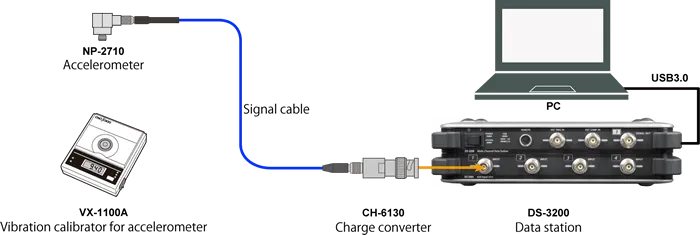
Figure1.The example of connection between the charge output type accelerometer and analyzer
The charge output type accelerometer cannot be directly connected to the DS-3000 Data station or CF-9000 FFT Analyzer. It is necessary to connect the products such as CH-1200A Charge amplifier and CH-6130 / 6140 Charge converter between them and convert the charge signal output from the accelerometer into the voltage signal.
The accelerometer with built-in preamplifier can be directly connected. NP-2000 series are charge output type, and NP-3000 series are built-in preamplifier. The simplest way to distinguish between them is to check with the calibration chart provided as standard in the accelerometer. The unit of sensitivity of the charge output type is pC/(m/s2), and the built-in preamplifier one is mV/(m/s2).
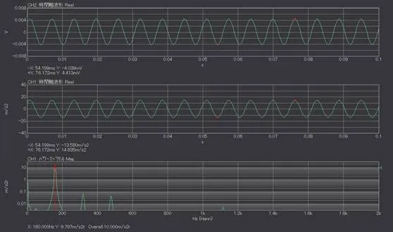
When NP-2710 charge output type accelerometer is connected to DS-3000 Data station via CH-6130 charge converter, and 10 m/s2, 159.2 Hz calibration signal of vibration calibrator for accelerometer is measured, the result is shown in Figure 2. By checking with calibrator, the sensitivity of the charge output type accelerometer is 0.297 pC/(m/s2). As the gain of CH-6130 charge converter is 1.0 mV/pC, the combined sensitivity of the accelerometer and CH-6130 charge converter is 0.297 mV/(m/s2). Since the magnitude of the calibration signal is 10 m/s2 in efficient value, 28. 2 m/s2 in both amplitudes, the calibration signal voltage is calculated to be 2. 97 mV in efficient value, 8. 40 mV in both amplitudes. The difference between the maximum and minimum values of the voltage waveform (upper row) is 8.45 mV, which is almost the same as the calibration signal voltage in both amplitudes.
The difference between the maximum and minimum values of the calibrated acceleration waveform (middle row) is 28.4 m/s2, which is almost the same as the calibration signal in both amplitudes. The component 160 Hz of power spectrum (lower row) as 9.80 m/s2, the overall value as 10.0 m/s2 are almost same as the calibration signal.
Fig.2 (Upper: voltage waveform, middle: acceleration waveform, lower: power spectrum) |
When turning off CCLD (constant current drive)
CCLD (constant current drive) is one of the mechanisms for supplying power to sensors and preamplifiers from analyzers. Some manufacturers call them IPC, IEPE, however, the mechanism is same. Since CH-6130/6140 charge converter operates in CCLD power, CCLD power is supplied from the analyzer or else.
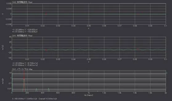
The calibration signal is shown in Figure 3 when the CCLD power from DS-3000 is off. The difference between the maximum and minimum values of the voltage waveform (upper row) is 70.8 μV. It is very small value compared with the actual value (8.40 mV). When the vertical axis of the graph is set to auto-scale, there is a possibility to perform the calibration without notice of the setting error as the similar waveform with sin-wave is displayed.
The acceleration waveform and its power spectrum are shown in Figures 3, in the middle, lower row) if the calibration is performed in the above setting. Since the total sensitivity is 0. 297 mV/ (m/s2), the EU value should be about 2.97E-4 V/EU, but the actual EU value is 2.58E-5 V/EU. It means that the sensitivity of accelerometer is only 0.0258 mV/(m/s2) as incorrect value.
Voltage waveform (upper), and acceleration waveform (middle) include DC offset. The DC offset volume is -189.2μV, -7.36 m/s2. If it is 0 V input, the analyzer shows not exactly 0 V but slightly off from 0 V. This is the DC offset error. According to Fig. 3, the DC offset is 189.2μV, but the acceleration waveform as if 7.36 m / s2 vibration is generated is obtained due to the incorrect calibration. This is caused by the incorrect calibration and DC offset error, it is not actual vibration.
Although it is not noticeable in the waveform in Fig. 3, if the measurement is performed with the power OFF of CCLD, a waveform with noise may be obtained.
When performing calibration with the vibration calibrator for accelerometer, you may notice the errors to confirm the voltage waveform before the calibration since the amplitude is abnormally small.
CCLD is also supplied from the analyzer, when using accelerometer with built-in preamplifier. As in the case above, when the calibration and the measurement are performed with the CCLD power supply turned off, the voltage is very small and the signal with DC offset and noise is obtained. In such case, please change the setting upon confirming if CCLD for the accelerometer is necessary or not.
Fig.3 The calibration signal when turning off CCLD
|
When the charge output type accelerometer connected without charge converter or charge amplifier
The charge output type accelerometer cannot be connected with CF-9000 FFT analyzer. CH-6130/6140 charge converter or CH-1200A charge amplifier are necessary in between them.
The charge converter or charge amplifier is the amplifier that converts a charge signal output from the accelerometer into a voltage signal. The input side is a miniature connector (No. 10-32 UNF), and the output side is a BNC connector. We also provide a product such as NP-0021 miniature/ BNC conversion adapter that only convert the connector of the sensor cable. It looks like a charge converter but cannot be a substitute for a charge converter.
Fig.4 CH-6130 Charge converter (left), NP-0021 Miniature/BNC conversion adapter (right)
|
Figure 5 is shown that the NP-2710 charge output type accelerometer is connected to a DS-3000 Data station via miniature / BNC adapter, and then the calibration signal at 10 m/s2, 159.2 Hz of the vibration calibrator for accelerometer is measured. This is not correct connection, measurement method.
The both amplitude should be 8.40 mV if the connection is correct. The difference between the maximum and minimum of voltage signal (upper) shows 6.37 mV, it apparently looks normal.
The sensitivity of accelerometer used is 0.297 pC/(m/s2), thus EU value should be around 2.97E-4 V/EU. It corresponds to the sensitivity of accelerometer, 0.226 mV (m/s2). The unit of sensitivity is different. If you focus only on numerical values, its digits look correct. Please check if the connection is correct before proceeding calibration and measurement.
Charge converter or charge amplifier
When the charge output type accelerometer is connected without charge converter or charge amplifier, the waveform shown looks apparently normal.
Half amplitude is Q[C], the time waveform of the voltage signal with frequency, f is shown in equation 1. t is time.
 Equation 1
When the charge signal differentiates, the current signal  is obtained.
 Equation 2
The voltage signal v(t) obtained by inputting the current signal into the analyzer with input impedance R [Ω] is shown in Equation 3.
 Equation 3
If the input impedance R is 1 MΩ, frequency f is 159.2 Hz, Equation 4 is as follow.
 Equation 4
When the charge signal with Q=1 pC is input, the voltage signal measured by analyzer is 1 mV as 109 times. The sensitivity obtained by incorrect calibration is almost the same as the value when the unit is changed from pC /(m/s2) to mV /(m/s2) without changing the numerical value.
If the value in pC is read as mV, the values match only when the vibration frequency is 159.2 Hz, and do not match at other frequencies. Even if the full acceleration signal is measured in this condition, the correct result cannot be obtained, so it is necessary to connect it correctly using a charge converter.
Charge converter or charge amplifier
When analyzing acceleration signals recorded by the accelerometer using an analyzer such as FFT analyzer or Data station, the calibration may be performed using the vibration calibrator for the accelerometer. If the calibration is performed with incorrect settings and connections, the correct acceleration signal seems to be observed, but the correct result is not obtained by the actual measurement.
This time we explain about the possible causes why the correct measurement results cannot be obtained with the accelerometer, one is turning off CCLD, another is connecting the charge output type accelerometer without charge converter or charge amplifier.
Even if the connections, settings are correct, calibration or measurement sometimes does not go smoothly. In such case, please confirm one by one such as disconnection of cable, failure of accelerometer/ analyzer, and electrical noise.
(YK)