No.1 Hammering and Trigger
An impulse hammer is an excitation hammer that has a built-in force sensor to measure a natural vibration frequency or perform modal analysis of a mechanical structure. By mounting an accelerometer on a measurement object and hitting it with an impulse hammer, excitation force signals and response acceleration signals are input to an FFT analyzer, which enables the measurement of the frequency response function and coherence function. From the analysis results, the natural frequency and damping ratio can be obtained, and modal analysis can be performed.
In hammering measurement, the force signals are used as the trigger source and data is captured in synchronization with them. However, if the analyzer is not set appropriately according to the actual signals, the trigger will not be applied, nor the data will be captured. Since there are many such cases, I will introduce how to set the analyzer for hammering measurement in this column.
●Initialization of analyzer settings
You don't know to which setting to revert after the analyzer was used for a particular measurement, especially another measurer used. In addition, unless the setting for hammering is ON, the correct data will not be imported.
Therefore, when using an FFT analyzer, it is recommended to initialize the settings of the analyzer and reset only the functions for hammering measurement. After completing all the settings, save the settings in the project file or panel condition, and load those for measurement from the next time onwards.
In particular, the following settings are not suitable for hammering measurement and they may cause data to not be imported correctly.
•Auto range
This function automatically changes the voltage range (input range) according to the magnitude of the input signal. Since the Auto range cannot support the instantaneous force signals, set the Auto range function to OFF.
•A/D over cancel
This function is one of the items in the sampling condition setting, and it will not capture data if the input signal voltage goes over the limit. This is a convenient function for actual measurement; however, turn it OFF until the adjustment is completed.
•Y-axis scale
Set to “default” so that the Y-axis scale of the graph is linked to the value in the voltage range. If the voltage range is not appropriate, or only minute signal is output due to the failure of hammer or sensor, the data will not be displayed, which makes it easier to notice abnormalities.
•Calculus function
This function enables to integrate acceleration signals and convert them into velocity and displacement signals. When checking the signals from the impulse hammer or sensor, turn it OFF. After completing the settings, confirm that the actual signals from the hammer or sensor can be measured correctly. Then, set this function as necessary.
●Temporary setting for hammering measurement
Connect an impulse hammer and an accelerometer to an analyzer. First, temporarily set the conditions of analyzer for hammering measurement so that the trigger is surely applied. Then, adjust the settings according to the actual signals and conditions.
•Input setting
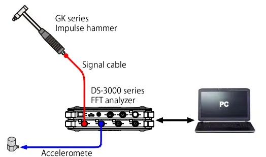
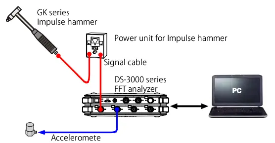
Set CCLD (power supply from a built-in preamplifier of hammer or accelerometer) to ON/OFF. When directly inputting from the impulse hammer as shown in Figure 1-1, set CCLD to ON. When inputting the signal from the power unit for the impulse hammer as shown in Figure 1-2, set CCLD to OFF. Set the same for the channel connected to an accelerometer.
•Unit calibration
Set the unit and sensitivity for the channel connected to the impulse hammer. Check the sensitivity of the impulse hammer in the calibration chart, and enter it (here, the sensitivity when using the hardest tip). If using an extender, enter the sensitivity with the extender. If the hammer sensitivity is 2.3 mV/N, set the unit name to "N", the EU type to "V/EU", and enter "0.0023" as the EU value converted from the unit to V/N. Leave the 0 dB reference value as 1 and the offset as 0 dB. Set the same for the channel connected to an accelerometer.
•Window function
Set the window function to Rectangular for all channels. If you want to use the Exponential window or Force window, change it after completing all the settings. However, seldom use Hanning window or Flat top window for hammering measurements.
•Frequency range
For the time being, set the frequency range to a higher value such as 20 kHz or 5 kHz. While checking the operation of the impulse hammer and trigger function, lower the frequency range to the actual frequency range.
•Trigger settings
Set the Input channel to the CH1 (the impulse hammer is connected), set the detection level to 5%, and set the hysteresis to 2%. Leave the Trigger position as “-32”.
●Adjusting voltage range
Attach the hardest tip to the tip of the impulse hammer. If the hammer comes with an extender, attach it. When using a power supply unit or sensor amplifier, turn it on. Set the voltage range of the analyzer to the lowest range. For the DS-3000 series, 10 mVrms is the lowest range. For the CF-9000 series, 1 Vrms. Hit the object by the impulse hammer as if it fell on the object with its own weight. If you keep the distance between the hammer and the object constant, you can hit with a constant force. If the Level Indicator LED is on in red, raise the voltage range gradually and hit it again until the LED does not turn on. Set the same for the channel connected to an accelerometer.
●Checking the operation of impulse hammer
Display the time axis waveform and power spectrum of the channel connected to the impulse hammer.
Click the TRIG button →the START button, and hit the object with the impulse hammer. Once the trigger is applied successfully, click the STOP button so that the waveform will be updated.
If the trigger is not applied, try hitting harder, or change to a harder object. If it does not work under these conditions, there is a possibility of a fault such as a broken cable or a hammer failure.
●Adjusting the detection level of trigger
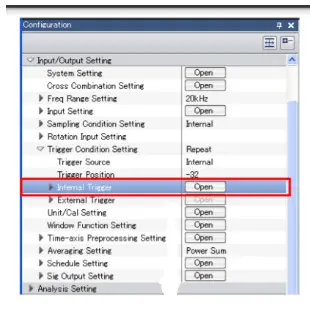
Open the Trigger Condition Setting to set the detection level.
For the DS-3000 series, select “Input/Output Setting” > “Trigger Condition Setting” > “Internal Trigger”, and click the “Open” button. As for the CF-9000 series, “HOME” > “Input” > “Trigger” > “Int Trigger”.
Set the trigger detection level to about 1/2 to 1/3 of the maximum value of the impulse hammer waveform. Normally, the hysteresis value can be about 2%. If the detection level is 5% or less, set the hysteresis value to about half of the detection level.
Click the waveform displayed in the trigger condition setting dialog, the detection level and position will be changed. Normally, the trigger position is set to “-32 or -100” where the waveform is easy to read. If the position is changed by clicking the waveform, return it to the original value.
Close the condition setting dialog, click START and hit with the impulse hammer to confirm if the trigger is applied.
●Adjusting tips and extenders of impulse hammer
Check the power spectrum of the force signals. If the power spectrum higher frequency range, change to the softer tip of impulse hammer. In addition, adjust the detection level to the maximum value of the force waveform.
If you change a tip, please confirm if the trigger is applied. If the trigger is not applied, please adjust as above.
If you don’t use an extender, confirm if the trigger is applied without the extender. If the trigger is not applied, adjust the voltage range again. If not yet, please lower the detection level and hysteresis.
When you change a tip or an extender, check the calibration chart to change the sensitivity in the unit calibration setting.
●Adjusting the frequency range
When you change the frequency range according to the desired frequency band, the trigger may not be applied. In this case, return the frequency range to the original value, lower it by a few levels and measure again. Adjust the detection level as well.
Do the same a few times to adjust the setting. If the detection level is changed, change the hysteresis, too.
●Other adjustment
If the force waveform looks small, try to lower the voltage range by one level. If the input signals go over by hitting, you can measure in that range. After changing the voltage range, set the detection level and the hysteresis in the trigger condition setting.
In addition, if you change the softer tip of impulse hammer, the above will be improved. The softer the tip, the lower the frequency band of the generated force. Check the actual measurement results of frequency response function and coherence function, and determine if the tip is appropriate.
●Summary
The procedure of measuring the frequency response function will continue, however, I explained the setting method until the trigger is applied in the hammering measurement. Even if the trigger is applied once and the measurement can be performed, it often happens that the trigger is not applied when the object to be measured is changed or the conditions are changed. In such cases, it will be useful to refer this column.
(Y·K)