No.5 Various measurement instrument: Dimension & Displacement Measurement
I will talk about dimension and displacement measurement in this column.
What do you imagine when you hear "measure dimensions or displacements"? Thinking about things around us, for example, when making shelves and tables, you need to accurately measure the dimensions of the boards. Or, when placing a table, it is also necessary to measure in advance whether the distance between the position where the chair is pulled back and forth (displacement amount) and the wall is sufficient.
In this way, it is very important to measure whether the dimensions (length, thickness, depth, angle, etc.) of various parts such as machines, devices, and products are within a certain reference range, and whether the traveled distance, position, rotation angle, etc. of machines or devices are as functional as they are, in order to determine their performance and specifications. This is the dimension and displacement measurement.
"Dimension" and "Displacement" are similar, but they have different meanings.
"Dimension measurement" is to measure "absolute values" such as length and thickness of objects.
"Displacement measurement" is to measure "relative value" such as the amount of movement from the reference position.
I will explain when, what kind of measurement instrument is used taking our measurement instrument as examples.
Sensor types
[ Dimension measurement ]
There are 3 types of sensors for dimension measurement.
- Contact type: Liner Gauge Sensors (BS/GS series)
ex) thickness, height, hole depth, etc. of metal processed products - Contact type: Rotary Encoder (RP/SP series)
ex) angle measurement of rotating object, feed amount of steel plate and paper - Non-contact type: Electrostatic capacitance type Gap Detector/Thickness Meter (VE/CL series)
ex) thickness measurement of steel plate, silicon wafer, resin film, etc.
[ Displacement measurement ]
There are 3 types of sensors for displacement measurement.
- Contact type: Liner Gauge Sensors (BS/GS series)
ex) deformation due to material load, shaft deflection of rotating object - Non-contact type: Electrostatic capacitance type Gap detector/Displacement meter
ex) shaft deflection of rotating object - Non-contact type: Laser Measurement System (LV-9000 series)
ex) performance evaluation and positioning accuracy of machine tool, which require finer resolution than micrometer and accuracy
For further detail information, please refer to the page: Dimension & Displacement
Operating principles of sensor and precautions
I will explain about the operating principle and precautions for using linear gauge sensors and rotary encoders, which are relatively popular.
(1) Liner Gauge Sensor
[ Operating principles ]
The basic structure of the liner gauge sensor is shown in Figure 1. Inside the sensor, a moving slit plate that moves together with a spindle is placed opposite to a fixed slit plate. Light and dark scales are printed on the slit plate at regular intervals. There are two fixed split plates which are 1/4 pitch off. The direction of movement (+/- direction) of the spindle can be determined by them. These slits are sandwiched in between the light source (LED) and the light-receiving element.
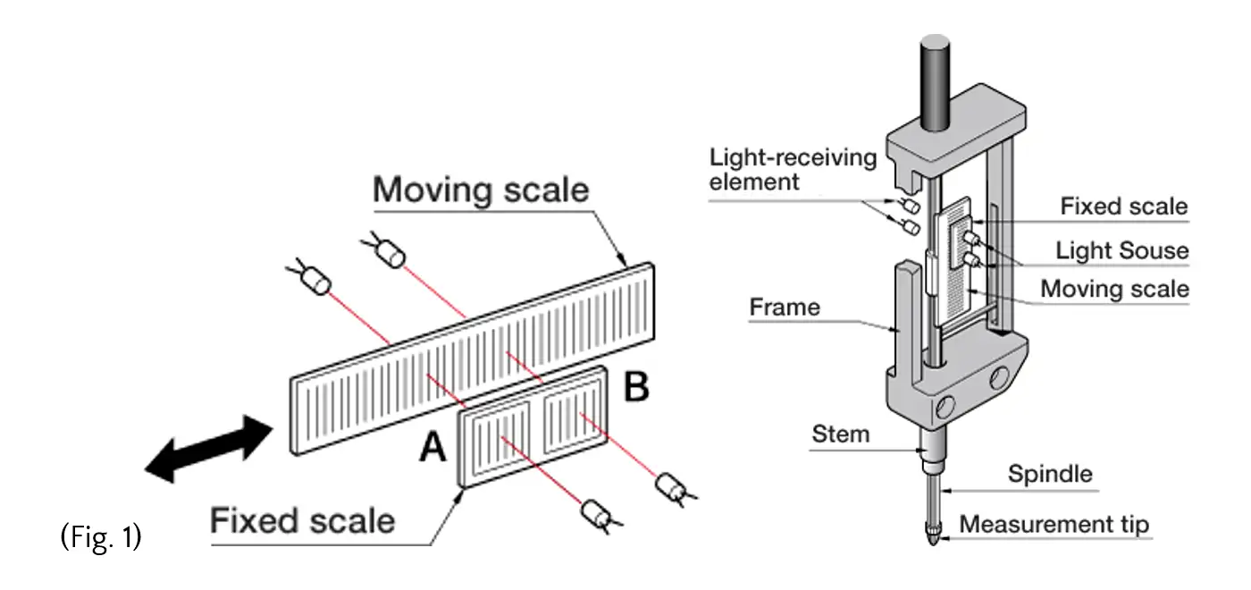
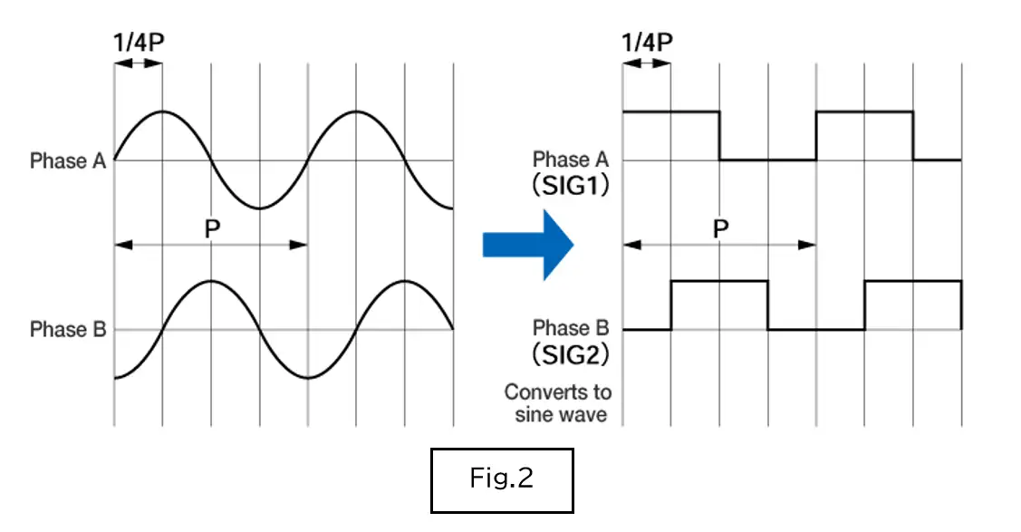
When the moving slit moves, the light passing through the fixed slit repeats light and dark. At this time, two square wave signals with 90° phase difference are output in the same period. The direction is determined by this phase lead or delay, addition/subtraction is calculated by the counter, and then displacement amount is measured.
[ Precautions ]
- Do not apply strong force to the lateral direction of the spindle.
(The impact may cause errors or damages when the spindle moves up and down.) - Please install the linear gauge itself away from the place with great vibration.
- Please install the spindle axis perpendicular to the measurement surface (reference surface).
(2) Rotary Encoder
[ Operating principles ]
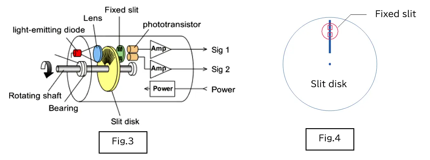
The basic structure of the rotary encoder is shown in Figure 3. A slit disk (moving) with equally spaced grid scales is attached to the rotating shaft axis of the rotary encoder. Opposite to the slit disk, another slit with equally spaced scales is fixed to the main unit of rotary encoder. (Fig.4)
This two slits are sandwiched in between light-emitting diode and phototransistor. When the slit disk rotates, the light emitted from the light-emitting diode is blocked for each slit pitch, and repeatedly blocked/passed through in proportion to the amount of rotation. This optical pulses are detected by two phototransistors, and converted into electrical signals as the output signals of encoder. The two output signals are adjusted to be offset by 90° from each other, and the rotation direction of the shaft is determined using the same principle as the linear gauge sensor explained earlier.
[ Precautions ]
- Do not apply a strong impact or a load exceeding the allowable load to the rotating shaft. - Install to align the rotating shaft with the coupling centering.
- It may be affected by noise from the power supply.
To avoid this, use a filter, noise-free power supply from another system, and separate it from the power supply where large amount of power flows during wiring.
When measuring dimensions and displacement, the sensor may break down depending on the installation conditions. Please pay attention to the mounting condition of the sensor.
Export restrictions
Since the Non-contact Thickness Meter VE/CL series*1 and the Laser Measurement System LV-9000 series are legally compliant products, the export license issued by Ministry of Industry is required when exporting these products or taking them out overseas.
*1 Combination of sensor and meter with resolution of 0.2 µm or less
(MO)