
![]()
![]()
![]()
Digital Torque Meter
TS-3200A
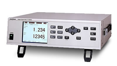
The TS-3200A is greatly improved in setting and
usability with large sized LCD which offers easy and clear view of
good contrast. Setting conditions and measurement data can be
displayed in the same screen.
Ten torque detection settings can be stored in memory, which is very convenient function when you use several torque detectors. The detector setting can be changed easily at the time for replacement.
Items on a main display can be selected and displayed simultaneously up to 7 items. As well as torque, rotation and output (W) of calculated data, each of maximum value, minimum value, peak to peak value, and ripple ratio can be selected to display. For example, average value and fluctuation range of torque can be monitored at the same time. In addition, the TS-3200A provides a variety of interfaces such as data outputs of 2 channels with analog voltage as standard, digital interfaces and additional functions as options. It may expand possibility of data communication with external equipment for control and data processing.
Features
Overview specifications
Torque signal measurement section
| ■ Input section | |
|---|---|
Amplification section |
Isolated unbalanced DC amplification |
Input signal |
Phase-differential type torque detector output signal |
Input impedance |
Approx. 2 kΩ (when input signal amplitude at 2 Vpp or less) |
Input frequency range |
200 Hz to 50 kHz |
Input signal amplitude range |
0.2 Vpp to 15 Vpp |
Connector |
TRC116 - 23A10 - 7F |
■ Setup section |
|
Capacity |
1 to 9999 |
Factor |
1 to 65535 |
Unit |
mNm, Nm, kNm |
Number of detection gears |
1 to 9999 P/R |
N-0 compensation |
Stored in each memory for CW and CCW directions |
Response |
Time constant can be settable among; 16 ms/31 ms/63 ms/125 ms/250 ms/500 ms/1 s/2 s/4 s/8 s/16 s/32 s/64 s |
Number of display digits |
Polarity + 4-digit or polarity + 5-digit, selectable |
■ Measurement section |
|
Measurement clock |
4.195 MHz |
Sample clock |
Sampling time for 1 data: 1/256 Hz (approx. 4 ms) |
■ Display section |
|
Number of display digits |
Polarity + 4-digit or 5-digit, selectable |
Unit |
mNm, Nm, kNm |
Display gate time setting |
1 s to 10 s (shared with a rotating section)or external gate |
Accuracy |
When combined with the detector (with 1 s gate time)
|
■ Output section |
|
Analog output |
Voltage output 0 to
±10 V/F.S. |
Response |
16 ms to 64 s depending on the time constant setting |
Accuracy |
When used in combination with a torque detector (The display renewal rate is 1 s.)
|
Temperature drift |
±0.01 %/F.S./ °C |
Rotational signal measurement section
| ■ Input section | |
|---|---|
| Sine wave (MP-9100 detector etc.) |
AC amplification Input impedance :10 kΩ or more Input frequency range :10 Hz to 100 kHz Input signal amplitude range :0.2 Vrms to 45 Vrms Connector :BNC |
| Square wave (MP-981 detector etc.) |
Unbalanced DC
amplification Input impedance: 10 kΩ or more Input frequency range: 1 Hz to 200 kHz (Guaranteed accuracy is 10 Hz or more.) Input signal amplitude range: HIGH level +4 to +30 V, LOW level +0.6 V or less Pulse width :2 μs or more Phase judgment as 90-degree phase difference signal input When SIG2 leads SIG1 by 90-degree: CW When SIG2 lags behind SIG1 by 90-degrees: CCW Power supply: 12 VDC, 100 mA Connector: R03-R6F |
| ■ Setup section | |
| Signal selection | MP-9100, MP-981 |
| Capacity | 10 to 100000 |
| Unit | r/min, r/s, Hz |
| Minimum measurement rpm setting | Rpm corresponding to 1Hz input frequency ≤ Setting < Capacity |
| Number of detection gear teeth | 1 to 99999 P/R |
| Ratio setting | ±1 to 9999/1 to 9999 |
| Rpm offset setting | Effective only for r/min ±1 to 9999 (Measured value = Actual measurement value – Rpm offset) |
| Response | Time constant setting 16 ms/31 ms/63 ms/125 ms/250 ms/500 ms/1 s/2 s/4 s/8 s/16 s/32 s/64 s |
| ■ Measurement section | |
| Measurement clock | 4.195 MHz |
| Sampling clock | Sampling time for one data: 1/256 Hz (about 4 ms) |
| ■ Display section | |
| Number of display digit | 5-digit |
| Unit | r/min, r/s, Hz |
| Display gate time setting | 1 s to 10 s (shared with the torque unit)or external gate |
| Accuracy | ±0.05 %/F.S. ±1 count (with 1 s gate time) |
| ■ Output section | |
| Analog output | Voltage output 0 to ±10 V/F.S. (2-phase signal input: CCW for minus output) (Attenuation setting of the F.S. is possible from 0.1 V to 10 V in 0.1 V steps.) |
| Response | 16 ms to 64 s depending on the time constant setting |
| Accuracy | ±0.1 %/F.S. ±10 mV (1 s average value) |
| Temperature drift | ±0.01 %/F.S./ °C |
Output (POWER) measurement section
| ■ Input section | |
|---|---|
| Calculated from the
measured torque and rpm Output (W) = 2π/ 60 x Torque (Nm) x Rpm (r/min) PS=0.7355 kW |
|
| ■ Setup section | |
| Capacity | 1 to 99999 |
| Unit | mW, kW, PS |
| ■ Response | |
| Time constant setting 16 ms/31 ms/63 ms/125 ms/250 ms/500 ms/1 s/2 s/4 s/8 s/16 s/32 s/64 s |
|
| ■ Display section | |
| Number of display digits | Polarity + 5-digit |
| Unit | mW, W, kW, PS |
| Display update gate time setting | 1 to 10 s (shared with torque and rotating section) |
| Accuracy | Torque display accuracy + Rpm display accuracy |
| ■ Output section | |
| Analog output | Voltage output 0 to ±10
V/F.S. (Attenuation setting of the F.S. is possible from 0.1 V to 10 V in 0.1 V steps.) |
| Response | 16 ms to 64 s depending on the time constant setting |
| Accuracy | Torque output section + Rpm output section accuracy (1 s average value) |
Display panel
| ■ Display section | |
|---|---|
Display |
Full dot-matrix type LCD panel (320 ×
240 dots) |
Main display |
1 to 3 step display can be selected. (torque, rpm, and output (POWER) |
Sub display |
Peak value (MAX, MIN, P-P) ripple factor |
Condition display |
Ready for measurement (READY), CLR input, torque signal input, rotational signal input, CW/CCW, comparator ON/OFF |
Item display |
Display pattern can be selected from 2-item display, 3-item display or 7-item display. (The item can be selected optionally.) |
■ Operation section |
|
| 16 keys of membrane switches (←,↑,↓,→,ENTER,ESC,MENU,CW/CCW,TRQ ZERO,TRIG,MEAS DISP, LCD ON/OFF,LOCK,SET VIEW,OPTION,CAL) | |
Interface section
| ■ Remote | |
|---|---|
| Clear input | Contact input (Set the measurement value forcibly to 0 when the constant closes.) |
| Rotational direction selection input | Contact input (CW/CCW torque zero point is selectable. The contact closes when CCW is selected.) |
| Trigger input | Contact input (Displayed as contact close when the external gate is selected, BCD is updated. OR with the front panel switch when the trigger function is used. ) |
| Trigger output | Contact output (Turns
ON/OFF synchronization with the display gate time.
Example: In case of 1 s gate, turns ON for 0.5 s and OFF
for 0.5 s.) *Synchronous operation of multiple TS-3200A is possible using trigger input or trigger output. |
| Ready output | Contact input (When the TS is in the torque measurement mode, the contact closes.) |
| Input section | In case of non-voltage
contact input Open voltage: 5.25 V or less Short-circuit current: 1 mA or less In case of voltage
input |
| Output section | Photo-MOS relay Load voltage: 30 VDC or less Load current: 100 mA or less On resistance: 10 Ω or less OFF resistance: 500 kΩ or more |
| Applicable connector | R03-PB8M (TAJIMI) |
| ■ Analog output | |
| Number of channels | 2-ch |
| Items | 2 items can be selected from torque, rpm, and output (POWER). |
| Connector | BNC |
| ■ Analog output 1ch addition (TS-0328 option) | |
Items |
Selectable from torque, rpm, and output (POWER). |
Connector |
BNC |
| ■ BCD output (TS-0323 option) | |
Number of channels |
2-ch |
Items |
2 items can be selected from torque, rpm, and output (POWER). |
Output update |
At intervals of gate setup time (0.1 to 10 s external) or sampling time |
Output format |
Positive logic open-collector output (Withstand voltage: 24 V max., residual voltage: 0.6 V max.) |
Connector |
Amphenol 50 P |
■ Comparator output (TS-0322A option) |
|
Number of channels |
4-ch |
Items |
Upper or lower level setting of the torque, rotational speed and power (output). |
Output format |
Photo-MOS relay |
Applicable connector |
RM12BPE-6S |
■ RS-232C(TS-0325 option) |
|
Standard |
Conforms to EIA and JIS X5101 |
Communication mode |
Asynchronous communication full-duplex mode |
Transmission rate(bps) |
1200, 2400, 4800, 9600, 19200 |
Character length |
8 bits |
Parity check |
None |
Stop bit |
1 |
Terminator |
CR + LF |
Applicable connector |
D-Sub 9-in, female |
■ GPIB(TS-0326 option) |
|
Electrical and mechanical specifications |
Common to IEEE 488-1978 |
Functional specifications |
SH1, AH1, T6, L4, SR1, RL1, PP0, DC1, DT1, C0 |
Address |
Talker/listener address setting (0 to 30) is possible. |
Terminator |
CR + LF |
■ Rotational pulse output (TS-0327 option) |
|
Channel |
1-ch |
Number of output pulse |
Same as the number of input pulses |
Output format |
TTL level |
Applicable connector |
BNC |
Other functions
| PeakHold | Measurement of peak value
between the trigger and the next trigger. (Display of torque, rotational speed, output (POWER), comparator) |
|---|---|
| Absolute value measurement | Display section, analog output, comparator |
| Ripple ratio measurement | Measurement of ripple
ratio between the trigger and the next trigger. (Display,
readout by communications only). Ripple rate (%) = (Torque peak to peak value between triggers/Torque average value between triggers) x 100 |
| Parameter setting memory | 10 kinds of backup memories and input of 20 characters are available. |
| Temperature compensation for factor | Temperature compensation for factor by recalculating the temperature value of torsion bar at the time of detector calibration and the temperature value of torsion bar in operating environment. |
| High-speed analog output (TS-0321A option) | 1 ms sample mode <Restrictions> ・No comparator output ・Fixed analog output time constant ・SS and MD series detectors cannot be used with. |
General specifications
| Power requirement | 100 to 240 VAC ± 10%, 50/60 Hz |
|---|---|
| Power consumption | 70 VA (100 VAC) or less |
| Insulation resistance | 10 MΩ or more (rated voltage at 500 VDC) |
| Withstand voltage | 1500 VAC for 1 minute |
| Operating temperature range | 0 to +40 °C |
| Operating humidity range | 90 % RH or less |
| Storage temperature range | -10 to +55 °C |
| Outer dimensions | 360 (W) × 99 (H) × 301 (D) mm |
| Accessories | Connector for REMOTE , AC power cable |
| Weight | Approx. 5 kg |
| Options |
|
Revised:2015/10/30