|
Applicable engines |
■ Gasoline and diesel
engines
■ General rotating objects |
|
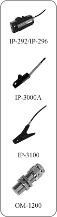
Compatible detectors |
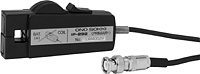
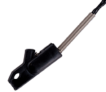
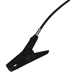
- IP-292/296 Ignition pulse detector
- IP-3000A/3100 Ignition pulse detector
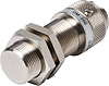
- OM-1200 Motor/gasoline engine RPM detector
- TTL signal output detectors
|
|
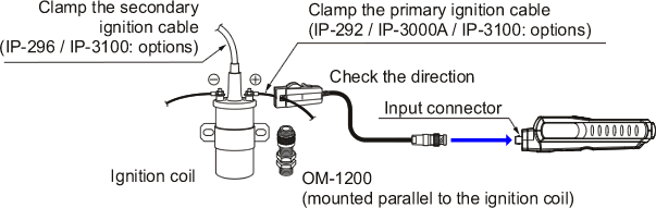
Object of measurement |
Ignition coil,
primary/secondary ignition cables, ECU rotation pulses
(5-V) |
|
Calculation method |
Cycle calculation method |
|
Measurement time |
Within 1 s + the time required for one cycle |
|
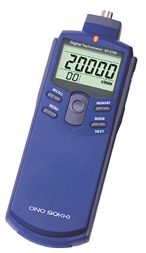
Display |
5-digit LCD, with backlight (character
height: 10.2 mm) |
|
Display update time |
1 ± 0.2 s |
|
Measurement units |
r/min (when the IP-292, IP-296, IP-3000A,
IP-3100 or
OM-1200 detector has been selected)
r/min, r/s, m/min, ms, COUNT (when a TTL signal output
detector has been selected) |
|
Measurement ranges |
| |
IP-292,
IP-296, IP-3000A, IP-3100 OM-1200 |
TTL signal output detector |
| r/min |
120 to 20000 |
100 to 99999 |
| r/s |
- |
1.66 to 99999 |
| m/min |
- |
0.3 to 99999 |
| COUNT |
- |
0 to 99999 |
| ms |
- |
0.6 to 300.0 |
*The number of pulses
per rotation (0.5 to 200.0 P/R) is freely
selectable. |
|
Measurement accuracy |
Displayed value* x (±0.02%)
±1 count
* The displayed value is the count value excluding
figures after the decimal point.
The measurement accuracy of the line speed depends on
the rotational (r/min) accuracy. |
|
Peak hold function |
Maximum value (MAX), minimum
value (MIN) |
|
Memory function |
20 data (MAX) |
|
Over-range function |
The over-range alarm (ERROR
mark) is displayed when the measured value exceeds the
display range. |
|
Rotation upper limit alarm function |
The upper limit alarm ( ↑
mark) is displayed when the number of rotations exceeds the
preset upper limit value. |
|
Line speed calculation function |
Calculates the line speed
from the preset diameter value (mm) and the measured
number of rotations |
|
Accumulating function |
Provides a cumulative count
of the input signal pulses |
|
Cycle measurement function |
Measures the input pulse cycle
(however, when the cycle is less than 1 s, measures the
mean value of the input pulses) |
|
Trigger level adjustment
function |
A rotary dial at the
right-hand side of the device is used to adjust the
trigger level. |
|
Analog output |
Output with respect to the
displayed rotation values Output voltage: 0 to 1 V/0 to FS
(FS is freely selectable)
Conversion method: 10-bit D/A conversion
Linearity: ±1%/FS
Output update time: Within 50 ms + the time required for 1
cycle
Temperature stability: ±0.05%/FS/°C (span & zero)
Setting error: ±0.5%/FS
Load resistance: At least 100 kΩ |
|
Monitor output |
Analog output for monitoring purposes after waveform
reshaping of the sensor signal Load resistance: At least
100 kΩ |
|
Pulse output |
1 pulse output per signal
detection
Output voltage: Hi level: At least +4.5 V. Lo level: Up to
+0.5 V
Output logic: Positive logic
Load resistance: At least 100 kΩ |
|
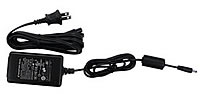
Power source |
Four AAA alkaline batteries or
exclusive AC adapter (PB-7090, Option) |
|
Battery life |
At least 16 hours (when the
backlight is OFF)
At least 8 hours (when the backlight is ON) |
|
Low battery alarm indicator |
A low battery alarm (LOW mark)
is displayed when the battery voltage falls below 4.4 V. |
|
Operating temperature range |
0 to 40°C |
|
Storage temperature range |
-10 to 50°C |
|
Outer dimensions |
189.5 (W) x 47.5 (H) x 66
(D) mm |
|
Weight |
Approx. 280 g (including
batteries) |
|
Accessories |
AAA alkaline batteries
× 4, Carrying case |