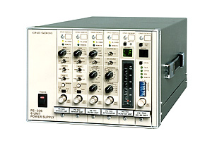
Power Supply Frame
PS-5506 Power Supply Frame - Flexible Signal
Processing System
PS-600 / 700 Series - Signal Processing Modules |
|
|
|
The PS-5506 flexible signal
processing system allows a user to select from various processing modules
such as an amplifier, filter and integrator.
It is possible to configure an optimal measuring system by incorporating
processing units into a multi-channel power supply frame.
In addition, the GP-IB interface module (option) is available for controlling
and reading the condition of each unit installed in the power supply frame
and for enabling measurement automation and remote control in combination
with an FFT analyzer or a computer. |
Features
-
Depending upon the measurement purpose, an
amplifier and signal processing modules can be selected and incorporated freely
-
Possible to flexibly expand and use the system
for different measurement application, by incorporating any other unit or changing
the module combination.
Specifications of PS-5506 Power Supply Frame
| Number
of module installed |
max. 6 modules
(for 25mm width of module) |
| Power
supply |
90 to 250
VAC, 50/60 Hz |
| Operating
temperature |
0 to +40°C |
| Operating
humidity |
80% R.H (with
no condensation) |
| Outer
dimensions |
210 (W) x
149 (H) x 400 (D) mm |
| Weight |
Approx. 5.1
kg |
Specifications of PS-602 Modular Type Sensor
Amplifier
|
Number of input |
1 channel |
|
Signal Amplifier Section |
Gain |
x 1,
x 10, x 100, selectable |
|
Gain error |
±0.5 % |
Frequency
response |
sensor amp.
mode |
3 Hz to 50
kHz (±0.1 dB)
0.5 Hz to 100 kHz (+1 dB to -3 dB) |
|
amp. mode |
DC to 50
kHz (±0.1 dB)
DC to 100 kHz (±1 dB) |
Phase
characteristics |
sensor amp.
mode |
+50° or better
at 0.5 Hz
+10° or better at 3 Hz
-20° or better at 50 kHz |
|
amp. mode |
-20° or better
at 50 kHz |
|
Low range cut filter |
fc = 2 Hz
(-3dB) 6dB / oct (on/off, selectable)
Gain : -0.1 dB
Phase : +10° or better at 20 Hz or more |
|
Distortion |
0.1% THD
or less |
|
Sensor power supply |
0.56mA ±
20%, 2.4mA ± 20%, selectable |
|
Input / Output Section |
Input Section |
sensor amp.
mode |
Input connector
: micro-dot (on front panel) |
amp.
mode |
Input
voltage |
±10 V max |
| Input
impedance |
100 kΩ± 20% |
| Input
type |
single ended
/ differential, selectable |
| Input
signal source |
EXT (power
supply frame)
LEFT (module) |
|
Output Section |
Output
impedance |
50 Ω± 10%
|
| Output
voltage |
± 10 V max
|
| Output
current |
5 mA max |
| Noise
level |
50 μVrms
(DC to 100 kHz) |
|
Power supply |
DC voltage
supplied from the PS-5500 |
|
Operating temperature |
0 to +40°C |
|
Operating humidity |
80% R.H (with
no condensation) |
|
Outer dimensions |
24.6 (W)
x 143 (H) x 247 (D) mm |
|
Weight |
Approx. 450
kg |
Specifications of PS-701 Filter Unit Features
-
Cutoff frequency between 1 Hz and 30 kHz, with
39-range selection
-
Excellent attenuation characteristics, 48 dB/oct
rolloff
-
Band pass selection for low pass (LPF), high
pass (HPF), and through (THRU)
|
Filter Section |
Filter mode |
LPF, HPF,
or THRU (through) |
|
Filter characteristics |
8 pole Butterworth
(48 dB/oct) |
|
Frequency response |
DC to 100
kHz (+0.5 dB to -3 dB) (THRU mode) |
|
Cutoff frequency |
1 Hz to 30
kHz with 39-range, selectable |
|
Cutoff frequency attenuation |
3 dB ± 1
dB except 3 dB ± 1.5 dB
(1 to 30 Hz, at 25°C) |
|
Input / Output Section |
Input Section |
|
Input voltage |
±10 V max |
|
Input impedance |
100 kΩ± 20% |
|
Input type |
single ended
/ differential, selectable |
|
Input signal source |
EXT (power
supply frame)
LEFT (module) |
|
Output Section |
Output
impedance |
50 Ω± 10%
|
| Output
voltage |
± 10 V max
|
| Output
current |
5 mA max |
| Noise
level |
500 μVrms
(DC to 100 kHz) |
|
Power supply |
DC voltage
supplied from the PS-5500 |
|
Operating temperature |
0 to +40°C |
|
Operating humidity |
80% R.H (with
no condensation) |
|
Outer dimensions |
24.6 (W)
x 143 (H) x 247 (D) mm |
|
Weight |
Approx. 500
kg |
Specifications of PS-702 Envelope & Peak Hold
Unit Features
-
Envelope filter, outputting an envelope of
vibration signal wave form
Using the sample hold circuit, enabling to detect the poles of the input vibration
signal and output voltage signal corresponding to the envelope.
-
Peak hold function is featuring high speed
mode with responds up to 100 kHz signal and output the max. value of the input
signal.
|
Input / Output Section |
Input Section |
|
Input voltage |
±10 V max |
|
Input impedance |
100 kΩ± 20% |
|
Input capacitance
|
Approx. 120
pF |
|
Input type |
single ended
/ differential, selectable
DC coupling |
|
Input signal source |
EXT (power
supply frame)
LEFT (module) |
|
Gain selection |
x 1, x 10,
x 100 |
|
Gain accuracy |
±0.3% (DC) |
|
Frequency response |
DC to 100
kHz (+0.3 dB to -0.5 dB) |
|
Reset Signal Input Section |
Reset signal |
Pulse (TTL,
neg, logic)
short by switch relays or front panel reset switch |
|
Voltage range |
-1V or greater
and +9V or less (allowable range) |
|
Reset pulse width |
5 μs or greater |
|
Output Section |
Output impedance |
50 Ω± 10%
|
|
Output voltage |
± 10 V max
|
|
Output current |
5 mA max |
|
Offset voltage |
± 2 mV max |
|
Over range |
+11 V or
greater, -11 or less |
|
Envelope Section |
Detection method |
Peak sample-hold
(pole value detection) |
|
Detection polarity |
Positive,
negative, whole wave, selectable |
|
Input frequency range |
1 Hz to 20
kHz |
|
Input voltage |
0.4 Vp-p
min, ± 10V max |
|
Conversion delay time |
(Input signal
cycle) x 3/2 or less |
|
Accuracy |
± 1 % FS
or less |
|
Distortion |
2 % THD or
less
(frequency ratio carrier-signal 100:1, modulation 80 %) |
|
Peak Hold Section |
Detection method |
Peak sample-hold
(pole value detection) |
|
Mode |
Normal |
Through rate |
0.6 V/μs
or greater
(responding up to 10 kHz, 10 Vo-p input sine) |
|
Droop |
50 mV/s or
less (at 20°C) |
|
Accuracy |
± 5 % FS
or less |
|
High Speed |
Through rate |
6 V/μs
or greater
(responding up to 100 kHz, 10 Vo-p input sine) |
|
Droop |
50 mV/s or
less (at 20°C) |
|
Accuracy |
± 5 % FS
or less |
|
Power supply |
DC voltage
supplied from the PS-5500 |
|
Operating temperature |
0 to +40°C |
|
Operating humidity |
80% R.H (with
no condensation) |
|
Outer dimensions |
24.6 (W)
x 143 (H) x 247 (D) mm |
|
Weight |
Approx. 450
kg |
Specifications of PS-703 Integrator Unit Features
|
Integration Section |
Integration |
Mode selection |
THRU (direct),
single integration, double integration |
|
Range |
Single
integration |
0.3, 3, 30,
300 Hz |
| Double
integration |
0.3, 1, 3,
10, 30, 100, 300 Hz |
|
Frequency response |
THRU |
0 dB (+1.0,
-3 dB), DC to 100 kHz |
| Integration |
0 dB (+1.0,
-3 dB), within the frequency range selected |
|
Amplifier |
Gain |
0, 10, 20,
30, 40 dB (±0.2 dB)
except 0 dB fixed in the THRU mode |
| G
to m/s2 conversion |
Converted
from G to m/s2,
enabling to output m/s2 by single integration or m/s by double
integration |
|
Input / Output Section |
Input Section |
Input
voltage |
±10 V max
|
| Input
impedance |
100 kΩ± 20% |
| Input
type |
single ended
/ differential, selectable
DC coupling |
| Allowable
range |
± 50 V max |
| Input
signal source |
EXT (power
supply frame)
LEFT (module) |
|
Output Section |
Output
impedance |
50 Ω± 10% |
| Output
voltage |
± 10 V max
|
| Output
current |
5 mA max |
|
Power supply |
DC voltage
supplied from the PS-5500 |
|
Operating temperature |
0 to +40°C |
|
Operating humidity |
80% R.H (with
no condensation) |
|
Outer dimensions |
24.6 (W)
x 143 (H) x 247 (D) mm |
|
Weight |
Approx. 450
kg |
Specifications of PS-706 GP-IB Unit Features
| Control Section |
Control function |
Unit to be
controlled selection
Unit condition setting / reading
Output level read from any unit
Analog signal output of any unit |
|
Signal Processing Section |
Function |
Peak level
storage during 1s interval of any unit and the most recent 1000s length
data storage |
|
Input Signal |
Output signal
of any unit
(external input is not available) |
|
Detection method |
Full-wave
quasi-peak detection
Rising time : 1.2 V/μs (input conversion)
Falling time : 7 V/μs (input conversion) |
|
A/D conversion |
10 bit sequential
comparison |
|
Voltage accuracy |
±0.2 dB (continuous
wave input, DC to 100 kHz)
+1 dB, -3 dB (single wave input, DC to 100 kHz) |
|
Memory capacity |
1000 data |
|
Conversion rate |
100 samples/s |
|
Output Section |
Output Section |
Output
voltage |
50 Ω± 10% |
| Output
impedance |
± 10 V max |
| Output
current |
± 10 mA max |
| Voltage
accuracy |
± 0.3 dB
or less |
| Noise
level |
0.2 Vrms
or less (input conversion, DC to 100 kHz) |
|
Power supply |
DC voltage
supplied from the PS-5500 |
|
Operating temperature |
0 to +40°C |
|
Operating humidity |
80% R.H (with
no condensation) |
|
Outer dimensions |
24.6 (W)
x 143 (H) x 247 (D) mm |
|
Weight |
Approx. 450
kg |
Specifications of PS-751 Monitor Unit Features
-
For monitoring of the signal output from each
modules on installed on the PS-5500
-
Peak value of the output signal from the PS
series modules can be detected and displayed on a bar-graph meter
-
High resolution meter with 50 graduation
-
Low pass filter (LPF) is equipped
|
Display Section |
Input signal |
Output signal
from other modules or external input signal selectable |
|
Frequency rage |
DC to 20
kHz (+0.2 dB to -3 dB) for sine wave, single half wave
DC to 100 kHz (+0.5 dB to -3 dB) for continuous sine wave |
|
Detection method |
Full-wave
quasi-peak detection
Rising time : 0.8 V/μs (input conversion)
Falling time : 2 V/s (input conversion) |
|
Display method |
Positive
or negative peak value (greater value is available) |
|
Monitor meter |
LED bar-graph
with 51 segments & OVER
Graduation : 0 to 100 %
Resolution : 2%
[unit output voltage measurement] 100 % indication at ± 10Vo-p
[external input measurement] 100% indication at full scale of each unit,
0.5s response time |
|
Low pass filter (LPF) |
10 kHz cutoff
frequency, 4-pole Butterworth, on/off selectable |
|
Control Section |
Monitor signal selection |
When the
PS-751 is installed in the first slot from the right of the PS-5500,
following position is selected.
* Any unit
* Left unit
When the PS-751 is installed in the other slot position on the PS-5500,
following position is selected.
* Left unit
* External input signal |
|
External input signal gain selection |
x 1, x 2,
x 5, x 10 (±0.2 dB) |
|
Input / Output Section |
External Input signal |
Input
impedance |
1 MΩ± 10
% |
| Input
type |
single ended
/ differential, selectable
DC coupling |
| Input
voltage range |
± 10 Vp,
± 5 Vp, ± 2 Vp, ± 1 Vp (4-range) |
| Allowable
voltage range |
± 50 Vp |
|
Input between modules |
Input
impedance |
50 MΩ± 5
% |
| Input
type |
Differential,
selectable, DC coupling |
| Input
voltage range |
± 10 Vp |
| Allowable
voltage range |
± 50 Vp |
|
Output |
Monitoring
signal output |
[External
input signal]
after passed through gain amplifier
[External input signal and input signal between modules]
before passed through filter |
| Output
impedance |
50 Ω± 10%
|
| Output
voltage |
± 10 V max
|
| Output
current |
5 mA max |
|
GP-IB function |
Valid only
when the PS-751 GP-IB module is installed in the first slot from the right
of the PS-5500 Power Supply Frame.
* Input signal selection
* Filter on / off |
|
Power supply |
DC voltage
supplied from the PS-5500 |
|
Operating temperature |
0 to +40°C |
|
Operating humidity |
80% R.H
(with no condensation) |
|
Outer dimensions |
24.6 (W)
x 143 (H) x 247 (D) mm |
|
Weight |
Approx.
500 kg |
|