Principle of Rotation Detector
Principle of electromagnetic rotation detector


MP-900/9000 series
This type can detect rotation signal by approaching closer to
the tip of the external detection gear mounted on the rotating
shaft. The detector consists of permanent magnet, detection coil
and yoke. When the magnetic material comes close to the yoke,
the magnetic flux passing the detection coil is changed. And
then the detection coil generates the inductive voltage
proportional to the frequency variation. The pulsation by the
magnetic flux [Frequency f = rotation speed(r/ min)× the number
of gears/60 (Hz)] is output as the rotation signal from the
detector.
The electromagnetic rotation detector is popularly used in many fields as a reliable measurement method with the following features.
- Simple structure
- No power supply required
- Compact
- Maintenance free
Principle of magneto-electric rotation detector
Magneto-electric rotation detector is made by applying a magneto-resistive element whose resistance value varies depending on the intensity of the magnetic field.
Normally, a constant magnetic field is applied by a magnet,
and the change in the magnetic field when the detection gear approaches the element is detected as a change in the resistance value.
The use of two elements reduces the effect on the detection magnetic flux due to factors such as gap changes, making it possible to output stable detection signals.
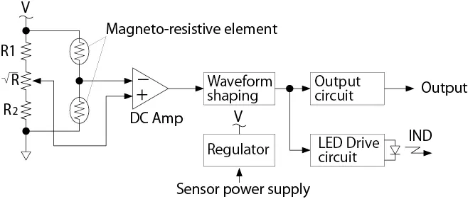
A bridge circuit is configured with magneto-resistive elements and electric resistive elements as shown in the figure, and the detection signal is taken as a differential output and amplified by a DC amplifier.
To adjust for variations in the resistance value of the magneto-resistive elements, a variable resistor is used in the bridge circuit and the signals are output to a DC amplifier.
When an involute gear is used as the detection gear, the output waveform becomes approximately a sine wave.
The output of the DC amplifier goes through a
waveform shaping circuit and is made into a rectangular wave.
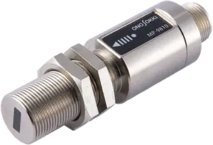
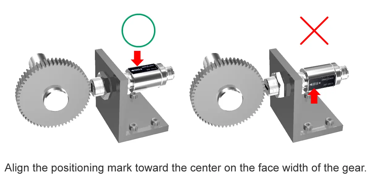
Magneto-resistive element is arranged at the tip of the detector. For correct gear detection, the detector has a positioning mark as a guide.
Principle of optical rotation detector
Measurable range of LG-9200
The LG-9200 Optical Detector, a reflective optical detector, employs an optical fiber at the tip, and is therefore suitable for detection of a rotating body. The detector incorporates a light source (LED) and photo sensor (photo-transistor), making it compact and easy to use. The use of the pulse modulation method makes the light source immune to the influence of disturbance light. The built-in operation indicator enables checking the operating status.
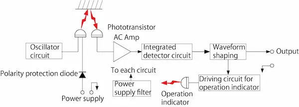
The oscillator circuit has a pulse modulation circuit that lights up the light source (LED) and is an astable multivibrator.
The pulse light emitted from the light source is reflected by the object to be detected,
and the output of the phototransistor is amplified to an appropriate level by the AC amplifier circuit,
then rectified and integrated by the detector circuit, and converted into a DC voltage.
In the waveform shaping circuit, when this DC voltage reaches the set level, the output level becomes HI, and when it falls below that level,
it becomes LO. When the output signal becomes the Hi level, the operation indicator lights up to check the operating status
Revised:2024/05/09